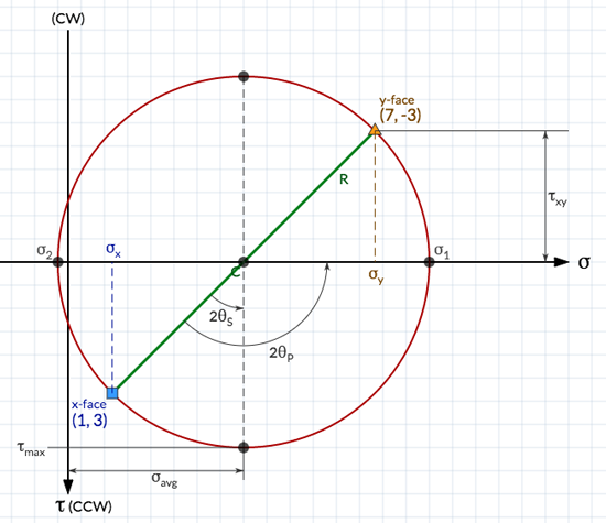
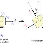
a.)Graphical plot showing transformation equation for plane stress is known as Mohr’s Circle
i. It provide visualization of relation between normal and shear stress
ii. Means of calculating principal stresses, principal angles, maximum shear stresses and stresses on inclined plane


 from the above equation by squaring and adding the above equation we will get


c.) Procedure for constructing Mohr’s circle when  are known
iii. Draw a set of coordinate axes with  abscissa (positive to the right) and
  as ordinate (positive downward)
iv. Locate the center C of the circle at the point having coordinates  and
and 
v. Locate point A, representing the stress conditions on the x face of the element shown in, by plotting its coordinate’s  and
and . Note that point A on the circle corresponds to
 . Also, note that the x face of the element is labeled “A” to show its correspondence with point A on the circle.
vi. Locate point B, representing the stress conditions on the y face of the element shown in, by plotting its coordinate’s  and
and . Note that point B on the circle corresponds to
 . Also, note that the y face of the element is labeled “B” to show its correspondence with point B on the circle.
vii. Draw a line from point A to point B. This line is a diameter of the circle and passes through the center C. Points A and B, representing the stresses on planes at 90° to each other, are at opposite ends of the diameter (and therefore are 180° apart on the circle).
viii. Using point C as the center, draw Mohr’s circle through points A and B. The circle drawn in this manner has radius R.


