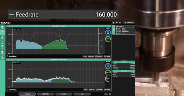
Uninterrupted machining is one of the challenges in front manufacturers to meet the production goals and customer satisfaction in terms of product quality. Tool wear is a critical factor which affects the productivity of a machining operation. Complete automation of a machining processrealizes when there is a successful prediction of tool (wear) state during the course of machining operation. Mechatronics based cutting tool-wear condition monitoring system is an integral part of automated tool rooms and unmanned factories. These systems predict the tool wearand give alarms to the system operator to prevent any damage to the machine tool and workpiece. Therefore it is essential to know how the mechatronics is helping in monitoring the tool wear. Tool wear can be observed in a variety of ways. These can be classified in two groups (Table1.2.1).
Table 1.2.1 Tool monitoring systems [2]
| Direct methods | Indirect methods |
| Electrical resistance | Torque and power |
| Optical measurements | Temperature |
| Machining hours | Vibration & acoustic emission |
| Contact sensing | Cutting forces & strain measurements |
Direct methods deal with the application of various sensing and measurement instruments such as micro-scope, machine/camera vision; radioactive techniques to measure the tool wear. The used or worn-out cutting tools will be taken to the metrology or inspection section of the toolroom or shop floor where they will be examined by using one of direct methods. However, these methods can easily be applied in practice when the cutting tool is not in contact with the work piece. Therefore they are called as offline tool monitoring system. Figure 1.2.2 shows a schematic of tool edge grinding or replacement scheme based on the measurement carried out using offline tool monitoring system. Offline methods are time consuming and difficult to employ during the course of an actual machining operation at the shop floor.

Figure 1.2.2 Off-line and on-line tool monitoring system for tool edge grinding
Indirect methods predict the condition of the cutting tool by analyzing the relationship between cutting conditions and response of machining process as a measurable quantity through sensor signals output such as force, acoustic emission, vibration, or current.
Figure 1.2.2 shows a typical example of an on-line tool monitoring system. It employs the cutting forces recoded during the real-time cutting operation to predict the tool- wear. The cutting forces can be sensed by using either piezo-electric or strain gauge based force transducer. A micro-processor based control system continuously monitors ‘conditioned’ signals received from the Data Acquisition System (DAS). It is generally programmed/trained with the past recorded empirical data for a wide range of process conditions for a variety of materials. ArtificialIntelligence (AI) tools such as Artificial Neural Network (ANN), Genetic Algorithm (GA) are used to train the microprocessor based system on a regular basis. Based on this training the control system takes the decision to change the tool or gives an alarm to the operator. Various steps followed in On-line approach to measure the tool wear and to take the appropriate action are shown in Figure 1.2.3.

Figure 1.2.3 Steps followed in an indirect tool monitoring system
A lot of academic as well as industrial research has been carried out on numerical and experimental studies of design, development and analysis of ‘Tool Condition Monitoring Systems’. Readers are suggested to browse various international journals such as International Journal ofAdvanced Manufacturing Technology (Springer), International Journal of Machine Tool and Manufacture; International Journal of Materials Processing Technology (Elsevier), etc. to learn more about these techniques.


