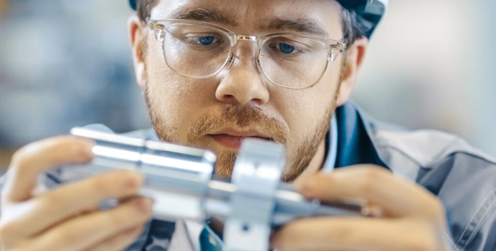
Visual testing (VT) is the oldest and most widely used nondestructive testing (NDT) techniques. It is typically the first step in the examination process to inspect a variety of product forms including castings, forgings, machined components and weld elements.
Compared to other techniques, visual testing is low in cost and easy to apply, and often eliminates the need for further types of testing. Some of the industries that use VT include structural steel, automotive, petrochemical, power generation, and aerospace.
QUALIFICATION:
The qualification of personnel conducting VT shall be as stipulated in personnel qualified as per document ASNT-SNT-TC-1A or as per ISO 9712 PCN level II.
All The personnel shall be capable of reading standard J-1 letters on standard Jaeger test type charts for near vision. Equivalent near vision tests are acceptable.
RESPONSIBILITES:
The Manager, QC shall be responsible for establishing and approving procedure and its implementation.
Qualified Inspection Engineer shall be responsible for the conduct of examination and documentation of visual examination.
APPLICABLE CODES AND REFERENCES:
ASME Code Sec.VIII Div 1, Div 2 and ASME B31.1
GENERAL REQUIREMENTS
Visual examination is defined as the observation of whatever portions of components, joints, and other piping elements that are exposed to such observation before, during, or after manufacture, fabrication, assembly, erection, inspection, testing or in service inspection. This examination may include verification of the applicable requirements for materials, components, dimensions, joint preparation, alignment, welding or joining, supports, assembly, and erection.
Lighting intensity should be 1000 lux minimum to properly inspect or examine affected areas or surfaces. A 100 W hand lamp at a distance of 500mm will provide 1000 lux light intensity
VISUAL EXAMINATION TOOLS & AIDS
– Visual aids such as flashlight, mirrors, magnifying lenses, cameras, or other suitable instrument.
– Mechanical aids for visual examination such as vernier caliper, micrometer, weld gages, high- low gauge (for measuring pipe joint alignment) etc.
– In some cases, remote visual examination may have to be substituted for direct examination.
– Remote visual examination may use visual aids such as mirrors, telescopes, borescopes, fibre optics, cameras, or other suitable instruments. Such systems shall have a resolution capability at least equivalent to that obtainable by direct visual examination
VISUAL EXAMINATION BEFORE WELDING
Physical Condition of Material or items:
-Surfaces of materials shall be free from defects, and imperfections, which may affect the quality of a weld. Edges of materials to be welded shall be free from scale, slag, rust, moistures, grease, or other foreign material that may impair welding quality.
-Edges of materials cut either by shearing or flame cutting that have notches, laps, loose slags, gouging marks shall be suitably removed before welding.
-Surface of base materials shall also be checked for possible manufacturing or handling defects.
Fit-up Inspection
The following shall be checked in conformance to approved WPS, drawing and / or any other applicable code requirements.
➟Alignment (The internal mis-alignment not to exceed 2.0 mm)
➟Root face or root land
➟Root opening.
➟Bevel angle.
➟Tack welds
VISUAL EXAMINATION DURING WELDING
The following shall be verified/monitored during welding for compliance with WPS:
➟Welding process.
➟Filler metal.
➟Flux or Shielding gas.
➟Preheat or inter-pass temperature.
➟Examination after back chip / back gouging (if applicable)
Arc strikes outside the area of intended weld should be avoided on any base metal.
VISUAL EXAMINATION AFTER WELDING
The weld shall be examined after completion for the following:
a. Acceptability of weld appearance as per the acceptance criteria
b.Dimensional requirements for welds (fillet size etc.)
VISUAL EXAMINATION DURING INSERVICE INSPECTION
The weld shall be examined for the following:
➟Acceptability of weld appearance as per the acceptance criteria
➟Dimensional requirements for welds (fillet size etc.)
➟Inservice induced visible discontinuities like crack erosion etc
REPORTING CRITERIA
Following indications in welds in pipe and piping components and parent metal surface under examination shall be reported as described under:
⇢Cracks — surface.
⇢Undercut on surface which is greater than 1⁄32 in. (1.0 mm) deep.
⇢Lack of fusion on surface.
⇢Incomplete penetration (applies only when inside surface is readily accessible).
⇢Any other linear indications greater than 3⁄16 in. (5.0 mm) long.
⇢Surface porosity with rounded indications having dimensions greater than 3⁄16 in. (5.0 mm) or four or more rounded indications separated by 1⁄16 in. (2.0 mm) or less edge to edge in any direction. Rounded indications are indications which are circular or elliptical with their length less than three times their width.
REPAIR AND RE-EXAMINATION
➻Any unacceptable indication shall be repaired by grinding, care shall be taken to avoid reducing weld metal or base metal thickness below the minimum required thickness.
➻ If required weld repairs shall be carried out using qualified procedures and welders.
➻The repaired area shall be re examined to ensure it meets the applicable requirements.
VISUAL EXAMINATION DOCUMENTATION
➟Visual Examination shall be reported on approved format
➟Name of the individual who carried out the visual examination shall be specified.
➟All visual examination records shall be available for review by AI.
Details of remote visual Inspection ( BOROSCOPY)
The boroscopy instruments have been designed for internal observation and inspection of machinery, equipment and structures that cannot be viewed from the outside
Before each use, prepare and inspect the instrument as instructed by manufacturer. The image quality is variable depending on the surface condition of the object and image capturing condition such as the brightness. The accuracy of the results obtained with this measurement technique is identified through experiments.
The object distance measurement shall measure the distance between the distal end of the optical adapter and the subject in a live or frozen image.
As the measurement is affected if the image of the subject is blurred, move the distal end of the scope slowly.
Operating procedure for boroscope shall be as under:
1. Startup: Display the image to be measured and press the MEAS/ENTER joystick.
2. Reference point specification: Place the cursor on each extremity of an object with a known length in the observed image and press the MEAS/ENTER joystick.
3. Reference quantity specification: When the reference length input message is displayed, input the known quantity tilting the MEAS/ENTER joystick then press the MEAS/ENTER joystick to enter it.
4. Measurement point specification: Place the cursor on each extremity of the measurement object and press the MEAS/ENTER joystick to measure its length.
During Operation of boroscope following caution points shall be observed:
✶Do not insert the scope into an operating machine as this could damage the scope.
✶Keep the insertion tube away from liquids other than water, saline, machine oil or light oil.
✶Avoid moistening the parts other than the insertion tube,
✶Release the angulation lock if it activated and gently withdraw the scope while observing the image on the monitor
✶Clean the insertion tube immediately after withdrawing the scope
✶Do not use a hard or abrasive cloth or brush to clean the scope, as they could cause damage to the instrument
✶Store the equipment under normal room temperature and humidity conditions. Make sure it is kept in good condition. Avoid areas that are subject to direct sunlight or radioactive rays.
✶Do not bend the scope by a radius below that given in the instruction manual (generally 30˚).


