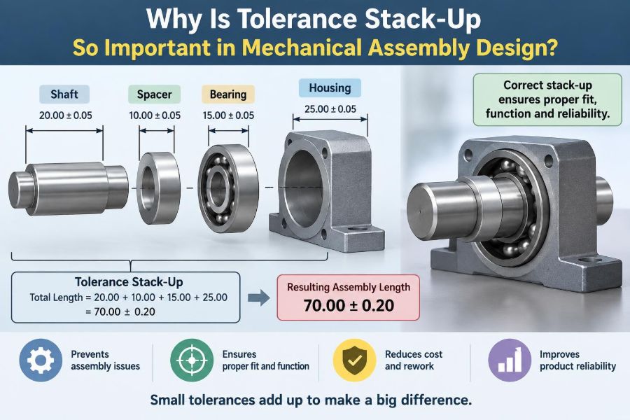

A shaft slides smoothly through a bearing on one production unit, then binds on the next. A housing cover appears perfectly machined, yet its mounting holes will not line up with the threaded holes beneath it. A latch closes during a bench test but rattles after the product reaches a hot environment.
These problems are often blamed on a single “bad part.” In many cases, every individual part is within its drawing tolerance. The failure comes from the way small, permitted variations combine when those parts become an assembly.
That combined variation is called tolerance stack-up. It is one of the central reasons that assembly design cannot be treated as the simple act of placing correctly dimensioned components together.
Understanding stack-up helps designers protect function, manufacturers avoid painful rework, and quality teams inspect the dimensions that truly matter. It turns tolerancing from a drawing requirement into a practical tool for making products that assemble and perform reliably.
🧩 What Tolerance Stack-Up Means
A tolerance is the permitted variation around a nominal dimension. For example, a plate specified as 100 mm long with a tolerance of ±0.10 mm may be acceptable anywhere from 99.90 mm to 100.10 mm, assuming the stated tolerance applies in that way.
A tolerance stack-up is the cumulative effect of several such variations along a path that controls a functional requirement. That requirement may be a gap, alignment, engagement depth, preload, clearance, or location of a feature.
The word “stack” does not mean that parts must literally be piled vertically. It refers to tolerances being added, subtracted, or otherwise combined through an assembly relationship.
🎯 Why Nominal Dimensions Are Not Enough
Nominal dimensions describe the ideal geometry. Real manufacturing produces a distribution of results around that ideal because cutting tools wear, fixtures shift slightly, material responds to processing, and measurement has uncertainty.
Designing only from nominal dimensions can create a false sense of security. Two nominally aligned holes may be shown in the same location on separate drawings, while their allowable positional variation makes interference possible in the assembled condition.
The useful question is not “Do the CAD models fit?” It is “Will acceptable real parts fit and function across the intended range of variation?”
📏 The Functional Requirement Comes First
Every stack-up analysis should begin with a functional requirement, sometimes called a functional condition. This is the measurable assembly outcome that must be protected.
Typical requirements include:
- minimum running clearance between moving parts,
- maximum gap at a seal or cosmetic interface,
- minimum thread engagement,
- allowable position error at a connector or fastener,
- bearing preload or end play, and
- engagement between gears, splines, or latches.
Without a defined requirement, a tolerance analysis can become an exercise in arithmetic with no engineering decision behind it. The end condition tells the team which dimensions belong in the chain and what failure looks like.
🔗 Building a Tolerance Chain
A tolerance chain is the sequence of dimensions, geometric controls, and interfaces that connect datums to the functional requirement. Think of locating a hole in a cover relative to a pin in the base: the chain may include base features, locating surfaces, cover dimensions, and clearance in the pin-hole interface.
Start at one functional boundary and trace physically through the assembly to the other boundary. Record each contributor in the direction of interest. A gap measured left to right, for example, should include only dimensions that influence that left-to-right position.
Good chains are closed and traceable. If an analyst cannot point to the physical feature represented by each term, the calculation is not yet dependable.
➕ The Basic Worst-Case Method
Worst-case analysis assumes every contributing dimension simultaneously reaches the limit that produces the least favorable assembly condition. For a simple linear clearance, the minimum clearance is found by combining the smallest clearance-producing terms and the largest clearance-consuming terms.
Suppose a nominal gap is 0.40 mm. If one component can grow by 0.10 mm and an opposing component can grow toward the gap by 0.15 mm, the minimum predicted gap is 0.15 mm, before considering other contributors.
This method is deliberately conservative. It answers a demanding question: can all conforming parts assemble even when their individual variations align in the worst possible direction?
🛡️ When Worst-Case Analysis Is Necessary
Worst-case stack-up is appropriate when failure is unacceptable and parts are not deliberately matched during assembly. Safety-related mechanisms, essential seals, interference-sensitive fits, replacement parts, and assemblies made by independent suppliers often require this level of protection.
It is also valuable in low-volume products where a small sample does not justify assumptions about production distributions. If a product must work with any compliant replacement part, relying on favorable statistical averaging may be risky.
The trade-off is cost. Guaranteed interchangeability can demand tighter tolerances, more capable processes, or a different architecture.
📊 Statistical Stack-Up and Its Purpose
Statistical analysis recognizes that it is unlikely for every independent dimension in a large assembly to land at its worst limit at the same time. Instead of adding all tolerance magnitudes directly, an analyst combines estimated variation using a statistical model.
A common simplified approach is root-sum-square, or RSS:
Assembly variation ≈ √(T₁² + T₂² + T₃² + ...)
Here, each term represents a compatible variation measure, not automatically any tolerance printed on a drawing. The method often predicts a smaller assembly variation than a worst-case sum, but it is not a permission slip to loosen dimensions blindly.
⚖️ Worst-Case Versus Statistical Thinking
| Approach | Best suited to | Main strength | Main limitation |
|---|---|---|---|
| Worst-case | Critical function and full interchangeability | Protects all limit combinations considered | May drive costly tight tolerances |
| Statistical | Stable, understood, higher-volume processes | Can balance yield and manufacturing cost | Depends on valid process and distribution assumptions |
| Hybrid | Assemblies with both critical and noncritical paths | Applies conservatism where it matters most | Requires clear engineering judgment |
Statistical models need evidence: process capability information, realistic distributions, meaningful independence assumptions, and a defined acceptable risk level. Correlated dimensions—such as features machined in the same setup—may move together rather than cancel randomly.
🚫 A Stack-Up Is Not Just Adding Plus-and-Minus Values
Simple arithmetic works only when the geometry and tolerance definitions are simple. Positional tolerances, angular errors, profile controls, runout, surface form, and flexible interfaces can influence the functional condition in ways that a one-dimensional chain does not capture.
For instance, a tilted face changes the gap differently at different points. A hole with position tolerance can shift in two planar directions. A cylindrical shaft can have size, straightness, and runout effects that matter differently depending on how it is supported.
Use the simplest model that represents the actual function, but do not simplify away the failure mechanism.
🧭 Datums Decide How Parts Locate
A datum is a theoretically exact reference used to establish the location or orientation of features. In an assembly, datum selection should reflect how a part is actually seated, clamped, located, and inspected.
Poor datum choices create hidden stack-up paths. A drawing may locate a critical hole from a convenient edge, while the assembly actually locates from a bore and a mounting face. Variation between that edge and the functional locating features then enters the assembly unnecessarily.
Dimension critical features from functional datums whenever practical. This reduces ambiguity and gives manufacturing and inspection a common reference system.
🧱 Part Interfaces Add Their Own Variation
Assembly interfaces are not perfectly rigid mathematical planes. Clearance in a pin-hole pair, play in a fastener joint, burrs on seating faces, and local surface irregularities can all alter final location.
A bolted cover is a familiar example. Before tightening, the cover can shift within fastener-hole clearance. Once tightened, friction and clamp force may lock it in a position that depends on assembly sequence and the direction of applied force.
Ignoring interface freedom often produces an analysis that looks precise but does not describe the real assembly.
🕳️ Clearance Fits Can Help or Hurt
Clearance is frequently introduced to make assembly easier, accommodate expansion, or allow adjustment. It is useful, but it also permits motion. If location is controlled by loose fasteners rather than dedicated features, the accumulated movement can be large compared with the tolerance of the machined parts.
Consider adding a pilot diameter, dowel pins, shoulders, tabs, or a constrained slot when repeatable location matters. The best locator should carry the locating function; ordinary fasteners should mainly provide clamp force.
More clearance is not automatically safer. It may prevent assembly interference while causing misalignment, noise, uneven loading, or an unacceptable visual gap.
📐 Geometric Dimensioning Changes the Analysis
Geometric dimensioning and tolerancing, commonly called GD&T, controls geometry in ways that coordinate ± dimensions often cannot. Position controls the location of an axis or center plane relative to datum references. Profile can control a complex surface. Perpendicularity, parallelism, and runout address orientation and rotation.
These controls must be interpreted according to the applicable drawing standard and the stated datum structure. Their effects are often represented as zones, not as a simple plus-or-minus shift along one axis.
For critical interfaces, a GD&T-aware stack-up analysis is usually more meaningful than converting every control into a rough linear tolerance.
🔩 Material Condition Modifiers Matter
Features of size may use modifiers such as maximum material condition (MMC) or least material condition (LMC), where permitted by the selected GD&T standard. These modifiers link allowable geometric variation to actual feature size.
For a clearance hole, a larger actual hole can provide additional positional tolerance, often called bonus tolerance. From an assembly perspective, the functional question is whether the mating pin or fastener can still enter and locate as intended.
Because modifier rules are standard-specific and easy to misapply, designers should verify interpretations with qualified GD&T knowledge rather than treating “bonus” as free, universal tolerance.
🌡️ Temperature Can Move the Limits
Parts change size with temperature. The approximate linear change is described by ΔL = αLΔT, where α is the material’s coefficient of thermal expansion, L is length, and ΔT is temperature change.
For short, same-material components in a stable room-temperature product, thermal effects may be small. In long assemblies, precision instruments, engines, outdoor equipment, or mixed-material designs, they can become a leading stack contributor.
A steel shaft inside an aluminum housing, for example, may see a changing fit as temperature changes because aluminum generally expands more over the same temperature interval. Analyze the intended operating range, not only the assembly bench condition.
💧 Environment and Time Also Affect Fit
Humidity, chemical exposure, creep, wear, corrosion, coating growth, and absorbed moisture can change dimensions or contact conditions over time. Polymer parts are especially likely to need environmental consideration because their response can depend on material grade, molding history, temperature, and moisture exposure.
A stack-up for a disposable indoor device may reasonably focus on manufactured dimensions. A long-life outdoor enclosure, medical device, or precision mechanism may require an aged or conditioned state as well.
The relevant question is: which condition defines successful function—freshly assembled, after transport, during use, or after years of service?
🏭 Manufacturing Processes Have Different Behaviors
Not all stated tolerances cost the same amount or remain equally stable. Turning, milling, grinding, stamping, molding, casting, additive manufacturing, and welded fabrication produce different patterns of variation, form error, residual stress, and achievable repeatability.
A tolerance that is reasonable on a ground diameter may be difficult or uneconomic on a large molded part. Likewise, a thin stamped feature may spring after forming, making a dimension measured in an unconstrained state misleading for the assembled condition.
Stack-up analysis should involve manufacturing knowledge early. A drawing can be mathematically complete while still asking a process to do something impractical.
🧪 Measurement Uncertainty Is Not Part Geometry
Inspection results include uncertainty from the gage, setup, operator technique, environmental conditions, and sampling method. A measurement system that cannot reliably distinguish good from marginal parts makes tolerance control difficult.
Measurement uncertainty should not simply be added to every design tolerance without thought. Its treatment depends on the quality system, acceptance rules, and the decision being made. But it must be acknowledged when tolerances approach the resolution or capability of the inspection method.
Design, metrology, and manufacturing need aligned definitions of how a feature is measured. Otherwise, “within tolerance” can mean different things to different teams.
🚗 Example: A Cover, a Pin, and a Misaligned Hole
Imagine a removable machine cover located by a pin on the base and retained by screws. The cover has a hole intended to pass over the pin. At nominal dimensions, the pin is centered perfectly in the hole.
In the real chain, the base pin has location variation, the cover hole has positional variation, the cover may shift in the screw clearances before tightening, and the pin and hole have size limits. If the radial freedom remaining after these effects is negative, some compliant combinations will not assemble.
The solution might be a larger clearance hole, a better datum scheme, a more accurately located pin, or a redesigned locating strategy. The correct choice depends on whether the pin is merely an assembly guide or a precision locator for another function.
⚙️ Example: Bearing End Play in a Shaft Assembly
In a simplified shaft assembly, the distance between two bearing seats competes with the combined widths of bearings, spacers, shoulders, and retaining elements. The difference may create end play, preload, or interference.
Too much end play can allow vibration, noise, or inaccurate positioning. Too much preload can increase friction, heat, and bearing stress. A few axial dimensions that seem individually modest may decide which condition occurs.
This kind of stack must also consider how components seat during assembly. A burr, a fillet interfering with a bearing chamfer, or an unaccounted coating can prevent a component from reaching its assumed datum face.
🧮 A Practical Analysis Workflow
- Define the functional requirement and its acceptable limits.
- Sketch the assembly in the critical direction or coordinate system.
- Identify functional datums and actual locating interfaces.
- Build the tolerance chain from one functional boundary to the other.
- Assign nominal values, limits, geometric controls, and interface clearances.
- Select worst-case, statistical, or hybrid treatment based on risk and process knowledge.
- Calculate the result, then review whether it matches physical assembly behavior.
- Document assumptions, conditions, and the dimensions that drive the outcome.
A spreadsheet can handle many linear chains. More complex three-dimensional assemblies may need specialized tolerance-analysis software, CAD-based tools, or simulation supported by experienced review.
🔍 Sensitivity Analysis Shows Where Effort Pays Off
Once the chain is built, examine which contributors have the strongest effect on the final condition. In a basic linear model, a dimension with a one-to-one relationship to the output has high sensitivity; a dimension with a small lever effect may matter less.
This prevents the common response of tightening everything. Improving a low-impact tolerance may add cost without solving the assembly problem, while changing one locating feature or one interface can create substantial margin.
Ask: if this contributor changes by a small amount, how much does the functional result change? That is often the most useful question in a design review.
💰 Tighter Tolerances Are Not a Universal Fix
Tightening a tolerance may require slower machining, more capable tooling, extra inspection, selective processing, higher scrap risk, or supplier development. It can also shift the burden to a dimension that is difficult to control consistently.
Before tightening a number, consider design alternatives:
- reduce the number of contributors in the chain,
- move a critical dimension to a common datum,
- add a robust locating feature,
- provide controlled adjustment,
- use a compliant element where function permits, or
- change the nominal clearance or engagement target.
A robust architecture usually costs less over the product life than a fragile architecture rescued by numerous extremely tight tolerances.
🧰 Adjustments and Selective Assembly Have Limits
Shims, eccentric features, slotted holes, calibration steps, and selective pairing can manage variation effectively. They are common engineering tools, not automatic signs of poor design.
However, they add labor, instructions, inventory complexity, error opportunities, and service challenges. Selective assembly also reduces interchangeability: a replacement part may not work without repeating the selection process.
Use these approaches deliberately when performance justifies them, and document the adjustment range, measurement method, and final acceptance condition.
👥 Tolerance Stack-Up Is a Cross-Functional Problem
The design engineer sees intended function. Manufacturing understands process behavior and fixturing. Quality understands inspection reality. Suppliers understand material and process limits. Assembly technicians often recognize fit problems before they appear in formal reports.
Early cross-functional review can reveal assumptions that a CAD model cannot show: a tool cannot access a datum, a coating masks a locating surface, a part can be assembled in multiple orientations, or a measurement reference is inaccessible.
Stack-up decisions improve when the people making and measuring the product can challenge the assumed assembly sequence and contact conditions.
⚠️ Common Stack-Up Mistakes
Several errors repeatedly make otherwise careful analyses unreliable:
- starting with dimensions rather than a functional requirement,
- using drawing datums that do not represent assembly location,
- omitting fastener clearance, part float, coatings, or seating effects,
- mixing total tolerance, ± tolerance, and statistical variation inconsistently,
- assuming independence without checking correlated process behavior,
- treating a two- or three-dimensional problem as one-dimensional, and
- failing to record assumptions for later design changes.
A calculation can be numerically correct and still be physically wrong if its model leaves out the mechanism that controls final position.
📝 Document Assumptions and Revision Triggers
A useful tolerance report states the assembly condition analyzed, temperature assumptions, component states, datum interpretation, calculation method, and source of each input. It should identify whether dimensions are preliminary targets, released drawing requirements, or measured process data.
It should also name revision triggers. A changed supplier, coating, material, manufacturing route, datum scheme, or assembly sequence can invalidate a previously acceptable analysis.
Clear documentation makes stack-up work reusable. It lets a later engineer understand why a particular tolerance exists instead of assuming it was chosen arbitrarily.
✅ Validate the Model With Physical Builds
Analysis predicts risk; prototypes and production evidence test the prediction. Build parts at representative limits when feasible, inspect critical interfaces, and observe the actual assembly sequence.
Do not validate only with carefully selected “best” prototype parts. A meaningful build explores expected variation, including parts near relevant limits and interfaces affected by real clamping or loading.
When physical results disagree with the analysis, investigate the model before simply changing the numbers. The discrepancy may expose an omitted contact, a misunderstood datum, or a process behavior that deserves attention.
📚 The Core Principle: Design for the Assembly, Not Isolated Parts
Tolerance stack-up matters because products function as assemblies. A part can meet its own drawing and still contribute to a failed fit, leak, misalignment, or poor mechanism performance when combined with other acceptable parts.
Robust assembly design connects functional requirements to real datum paths, realistic manufacturing variation, interface behavior, environmental conditions, and verification methods. It also distinguishes situations needing guaranteed worst-case performance from those where disciplined statistical control is appropriate.
The goal is not the tightest possible drawing. The goal is enough controlled margin for the product to assemble and work under its intended conditions at a sensible manufacturing cost.
When designers analyze how variation travels through an assembly, tolerances become a deliberate engineering strategy rather than a collection of isolated numbers. That shift produces clearer drawings, smoother builds, and more dependable products. ⚙️📏🔩