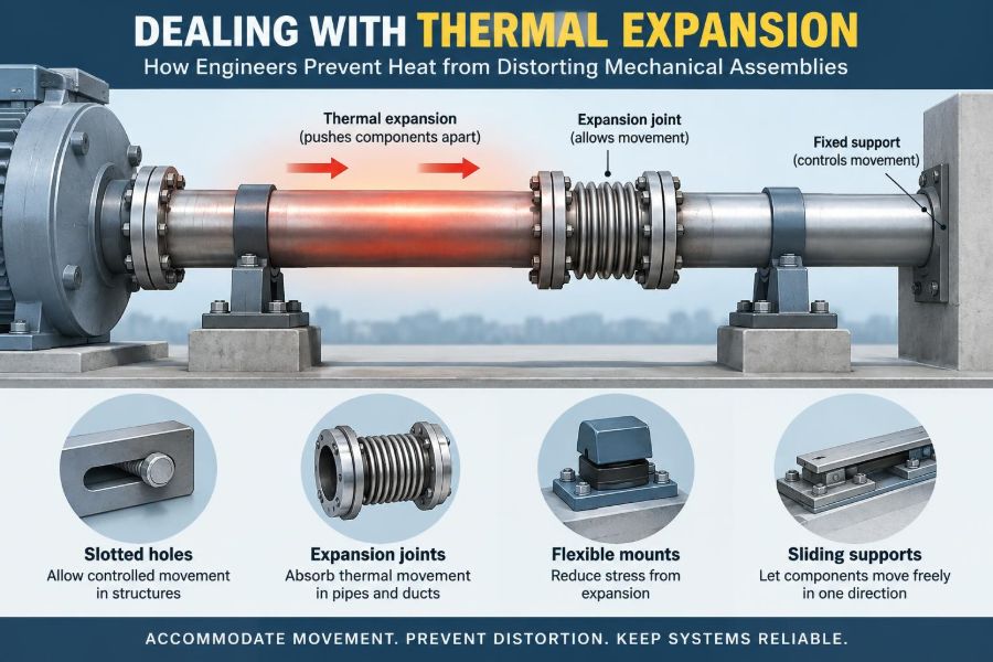

A machine can be perfectly aligned on the assembly floor and still run poorly once it warms up. A pump begins to rub, a precision slide starts to bind, bolts lose preload, or a long pipe pushes hard against its supports. Nothing may be “wrong” with the original dimensions; the temperature simply changed.
That is the everyday reality of thermal expansion. Solids usually grow when heated and shrink when cooled, often by amounts too small to notice with the eye but large enough to matter in machinery built to tight tolerances.
Engineers do not try to eliminate this movement. Instead, they predict it, decide where it can safely occur, and prevent it from becoming stress, distortion, leakage, or misalignment.
From a household thermostat to a gas turbine, success depends on a simple design habit: treat temperature change as a load case, not as an afterthought.
🌡️ Thermal Expansion Starts With a Simple Physical Change
Thermal expansion is the change in a material’s dimensions caused by a change in temperature. When a solid is heated, its atoms vibrate more vigorously and, on average, occupy slightly greater spacing.
Most engineering materials expand in all directions. A long steel shaft becomes longer, but its diameter also increases slightly. For many assemblies, the lengthwise change is the dominant concern because long dimensions magnify the total movement.
Cooling reverses the trend. This is useful in shrink fitting, but it can also create clearance, reduce clamping force, or crack a constrained component.
📐 The Core Equation Engineers Use
For a uniform component operating within a modest temperature range, linear expansion is commonly estimated with:
ΔL = α × L₀ × ΔTHere, ΔL is the change in length, α is the coefficient of linear thermal expansion, L₀ is the original length, and ΔT is the temperature change.
The equation is straightforward, but its implications are easy to underestimate. A small coefficient multiplied by a long rail and a large temperature swing can produce movement far beyond the available clearance.
For example, a hypothetical 2 m aluminum member heated by 50°C expands substantially more than an equal steel member under the same conditions. The exact result depends on the alloy’s coefficient, which should be taken from an appropriate material-data source for final design work.
🧱 Why Material Choice Changes the Problem
Materials do not expand at the same rate. Aluminum alloys generally expand more than steels; many plastics expand much more than common metals. Specialty alloys and composites can be selected when dimensional stability is unusually important.
| Material family | Relative expansion tendency | Common design implication |
|---|---|---|
| Carbon and alloy steels | Moderate | Often manageable with conventional clearances and joints |
| Aluminum alloys | Higher than steel | Rails, housings, and frames need added movement allowance |
| Stainless steels | Varies by grade, often moderate to relatively high | Check the actual grade rather than assuming carbon-steel behavior |
| Plastics | Often high | Slots, flexible features, and broad tolerances are frequently needed |
| Fiber-reinforced composites | Direction-dependent | Expansion must be evaluated along fiber and transverse directions |
Material selection is not just a strength, weight, corrosion, or cost decision. When dissimilar parts are joined, their different expansion rates can govern the entire interface design.
↔️ Differential Expansion Is Usually the Real Challenge
A single, freely expanding bar is rarely troublesome. Problems arise when connected parts attempt to change size by different amounts or when one part is prevented from moving.
Consider an aluminum plate bolted to a steel frame. As the assembly heats, the aluminum wants to grow more. If every bolt hole tightly fixes the plate, the plate cannot follow its natural movement and internal stresses develop.
Differential thermal expansion is therefore often more significant than absolute expansion. Engineers ask not only “How much will this part grow?” but also “How much will it grow relative to the part holding it?”
🔒 Restraint Turns Free Movement Into Stress
If a component can expand freely, temperature change mainly causes displacement. If it is fully restrained, that same tendency to expand becomes thermal stress.
In an idealized uniaxial case, the stress can be estimated from elastic modulus, thermal expansion coefficient, and temperature change. Real assemblies are more complicated because joints slip, structures bend, contact conditions change, and temperatures are often nonuniform.
Still, the design lesson is durable: restriction is what makes expansion dangerous. A feature that looks rigid and well-supported can become overconstrained when heated.
🌈 Uniform Heating and Temperature Gradients Are Different Loads
Uniform heating changes a part’s overall dimensions. A temperature gradient changes dimensions unevenly, which can bend, twist, or locally distort a component even when its ends are free.
A long beam heated more on its top surface than its bottom surface tends to curve because the hotter side wants to become longer. A thick plate with a hot face and cool back can develop through-thickness stress.
Gradients are common during startup, rapid braking, welding, machining, induction heating, and intermittent process operation. Steady-state calculations alone may miss the most demanding condition.
🧭 The First Design Question: Where Should Movement Go?
Good thermal-expansion design starts by deliberately choosing a reference point. One location is fixed to establish position; other locations are allowed to move in controlled directions.
This approach prevents a structure from “choosing” its own path through bent brackets, loaded fasteners, or rubbing interfaces. The goal is not simply to add looseness everywhere. It is to provide intentional freedom with maintained function.
A linear guide, for instance, may be fixed at one end and supported by a floating arrangement at the other. The fixed end defines accuracy; the floating end absorbs growth.
📌 Fixed and Floating Supports Control Long Structures
Fixed-and-floating support schemes appear in shafts, rails, heat exchangers, piping, and machine beds. Their details vary, but the underlying logic is the same.
- A fixed support locates the component and reacts forces in selected directions.
- A floating support carries the required load while permitting axial or lateral thermal movement.
- The permitted direction must match the actual expansion path.
Two “fixed” supports on a long member may appear stronger, yet they can generate high thermal loads. Conversely, too much freedom can allow vibration or loss of alignment. Support design is a balance between constraint and controlled mobility.
🕳️ Slots and Oversized Holes Create Planned Clearance
Slotted holes are one of the simplest ways to accommodate expansion between bolted components. A bolt can clamp the parts together while the slot allows relative movement along the anticipated growth direction.
The slot must be long enough for predicted movement, manufacturing tolerance, installation variation, and an appropriate margin. It should not be used casually where joint slip would compromise alignment, sealing, fatigue life, or safety.
Oversized holes can help in less precise joints, but they do not guide movement as clearly as slots. Washers, bearing area, and the expected contact path all need attention.
🪗 Expansion Joints Protect Pipes and Ducts
Piping systems can move significantly because their runs are long and their operating temperatures may differ greatly from installation conditions. If that movement is locked in, loads can be transferred into anchors, valves, pumps, vessels, and building structures.
Expansion loops use the flexibility of pipe bends and straight legs to absorb movement. Bellows-type expansion joints provide a compact alternative, but they require careful guidance, anchoring, pressure-thrust consideration, and fatigue assessment.
A flexible element is not a universal remedy. Misapplied bellows can fail early if lateral offset, angular rotation, vibration, or inadequate restraints exceed their intended capability.
🧩 Sliding Interfaces Need Low Friction and Proper Guidance
Many assemblies accommodate growth by allowing one part to slide against another. Examples include pipe shoes on supports, sliding machine covers, heat-exchanger components, and structural interfaces.
For sliding to work reliably, the designer must consider surface pressure, friction, corrosion, contamination, lubrication, and the possibility of stick-slip motion. A surface that slides easily in a clean prototype may seize after years in a damp or dusty environment.
Guides should permit the desired axis of movement while restraining the others. Uncontrolled sliding can introduce side loads, rattle, or positional drift.
🌀 Bearings Must Accommodate Shaft Growth
Rotating shafts often experience axial thermal growth from friction, process heat, or nearby hot components. Bearing arrangements must prevent that growth from creating excessive preload or axial force.
A common arrangement uses one locating bearing set to establish axial position and one non-locating bearing set that permits axial displacement. The exact implementation depends on bearing type, housing geometry, fits, speed, and load direction.
Simply clamping both bearings tightly in both directions can be a costly mistake. As the shaft grows, the system may develop internal load, elevated temperature, noise, and reduced bearing life.
🔩 Bolted Joints Can Lose or Gain Clamp Load
A bolt and the parts it clamps form a spring system. Temperature changes alter their lengths, and dissimilar materials can change the preload significantly.
If a steel bolt clamps an aluminum joint, the aluminum may expand more as temperature rises. Depending on geometry and temperature distribution, this can reduce bolt tension and joint clamping force. Other arrangements can increase tension instead.
Designers consider grip length, bolt material, washer selection, joint stiffness, temperature exposure, and relaxation behavior. At elevated temperature, creep and stress relaxation may further reduce preload over time, especially in some gasketed or polymer-containing joints.
🧷 Gaskets Need Movement Without Leakage
Seals are particularly sensitive because they need enough contact pressure to prevent leakage but must also survive relative movement, cycling, and changing material stiffness.
A rigidly constrained flange system may distort as it heats. That distortion can unload one portion of a gasket while overcompressing another. Flatness, bolt pattern, flange thickness, and temperature distribution all matter.
In dynamic equipment, seal selection must account for shaft growth, housing expansion, runout, pressure, and chemical compatibility. Thermal movement should be treated as part of the seal’s working displacement, not merely as a secondary condition.
🧊 Interference Fits Can Tighten or Loosen With Heat
Interference fits transmit torque or retain components through contact pressure. Their behavior changes when the shaft and hub have different temperatures or different expansion coefficients.
Heating a hub is often used deliberately during assembly because its bore enlarges temporarily. In service, however, a hotter shaft inside a cooler hub can increase interference, while a hotter hub can reduce it.
Final fit calculations should include manufacturing tolerances, material properties, expected temperature range, surface condition, and the stresses induced in both components. A fit that works at room temperature is not automatically suitable at operating temperature.
🧱 Composite and Bonded Assemblies Need Extra Care
Adhesively bonded joints and composite structures can be vulnerable to mismatch between materials. A metal insert bonded into a polymer or composite part may pull against the surrounding material during thermal cycling.
Because composites are anisotropic, their expansion depends on direction. Fibers may strongly limit expansion along their length while the matrix-rich transverse direction changes more substantially.
Design options include compliant adhesive layers, larger bond areas, mechanically tolerant joint shapes, matched materials, and controlled cure processes. Local stress concentrations around inserts and sharp geometry changes deserve particular scrutiny.
🧰 Clearance Is a Functional Dimension, Not Empty Space
Clearance allows moving parts to avoid interference, but temperature can consume it. A piston and cylinder, a valve spool and bore, or an electrical connector housing may have very different clearances at assembly and at operating temperature.
Engineers examine the worst combination of dimensions: maximum component size, minimum mating opening, and the temperature condition that most reduces the gap. Tolerance stack-up is essential because a nominal calculation may hide an unfavorable build.
Too much clearance is not always safer. It can increase leakage, noise, impact, vibration, or positional error. The correct value is the one that preserves function across the intended thermal envelope.
🧪 Transient Conditions Often Govern the Design
A system may be safe after all components reach the same steady operating temperature, yet fail during warm-up or cool-down. This happens because different parts heat and cool at different rates.
Imagine a steel shaft running through an aluminum housing. If the housing warms much faster, bearing fits and clearances may briefly become very different from their steady-state values. Startup procedures and heating rates can therefore be design variables.
Thermal cycling also matters. Repeated expansion and contraction can produce fatigue in joints, fretting at interfaces, cracking in coatings, and gradual loosening in fasteners.
🔥 Heat Sources Are Often Less Obvious Than Expected
Not every thermal problem begins with a furnace or hot fluid. Friction in bearings, electrical resistance, sunlight, nearby motors, welding, machining, and poor ventilation can produce meaningful local heating.
In precision equipment, even hands resting on a frame or a changing room temperature can affect measurement stability. In outdoor machinery, one side may face direct sun while the shaded side remains cooler.
A useful thermal review maps both the expected heat sources and the paths through which heat enters or leaves each component: conduction, convection, radiation, and sometimes internal generation.
🧠 Symmetry Can Reduce Distortion
Symmetrical geometry and heating conditions tend to reduce unwanted bending because opposite sides expand similarly. This is why balanced layouts are valuable in precision frames, brake components, tooling, and electronic enclosures.
When symmetry is impossible, designers may intentionally place features to counter expected movement. For example, sensitive sensors can be located near a thermal reference, or matched materials can be arranged around a centerline.
Compensation should be based on a credible thermal model or test evidence. Guessing at a “balancing” feature can create a new distortion mode under a different operating condition.
📏 Design From the Operating Datum, Not Only the Assembly Datum
A datum is the reference from which a dimension or position is controlled. In thermal design, the best assembly datum is not always the best functional datum.
If a sensor must maintain a fixed gap to a hot process surface, its mounting reference should be selected with operating movement in mind. Referencing it to a distant frame that expands differently may make cold assembly easy but hot performance poor.
This is sometimes called designing for the functional condition: define what must remain aligned, then arrange growth around that requirement.
💻 Analysis Tools Help, but Inputs Matter More
Hand calculations are excellent for early estimates and for checking whether a detailed model makes physical sense. Finite element analysis can then evaluate complex geometry, contacts, gradients, and stress concentrations.
Thermal-structural analysis is only as trustworthy as its assumptions. Material properties may vary with temperature, contact conductance can be uncertain, and boundary conditions may be difficult to represent.
Use analysis to compare design alternatives and identify sensitive assumptions. Do not treat a colorful deformation plot as proof that an assembly will behave exactly as shown.
🧫 Testing Should Reproduce Real Constraints
A thermal test that heats a loose component on a bench may confirm its free expansion but reveal little about an installed assembly. The fixture, mounting sequence, loads, cooling paths, and measurement locations should resemble actual use as closely as practical.
Useful measurements may include displacement, bolt preload, strain, temperature at multiple locations, bearing torque, leakage, and alignment. Repeated cycling is often more revealing than one slow heat-up.
Testing also exposes effects that simple models may miss, such as friction locking, uneven contact, assembly variation, insulation gaps, and local heat sources.
⚠️ Common Mistake: Assuming Room-Temperature Fits Are Enough
Many failures begin with drawings that specify an excellent room-temperature fit without defining the operating temperature range. A close sliding fit may seize, a press fit may relax, or a bearing arrangement may preload unexpectedly.
The remedy is to document the relevant temperature conditions on the design basis. Include normal operation, startup, shutdown, transport, storage, and credible abnormal conditions where they affect function or safety.
Temperature is not just an environmental note; it changes the dimensions that the drawing controls.
⚠️ Common Mistake: Overconstraining “For Strength”
Adding more fasteners, stiffer brackets, or additional hard stops can make an assembly appear robust. But if these features block legitimate expansion, they may merely transfer thermal loads into weaker or more sensitive locations.
Instead, distinguish the directions that need restraint from those that need freedom. A support can be stiff vertically, guided laterally, and free axially—all in the same component.
Constraint should be purposeful. The strongest-looking arrangement is not necessarily the most durable one.
⚠️ Common Mistake: Ignoring Assembly Sequence
Assembly procedures influence the thermal state and freedom of a joint. Tightening fasteners in the wrong order can lock a plate into a stressed position, while installing a floating support as if it were fixed defeats its purpose.
Drawings and work instructions should clearly identify fixed points, sliding surfaces, lubricant requirements, torque procedures, and any temperature-controlled assembly steps. Ambiguity at the factory floor can undo a careful design.
Service procedures matter too. Replacement parts, repainting, corrosion products, or substituted washers can change a joint’s ability to move.
🛠️ A Practical Thermal Expansion Design Workflow
A disciplined workflow makes thermal expansion manageable before it becomes a failure investigation.
- Define the temperature range, including gradients and transients.
- Identify dimensions and interfaces that control function.
- Gather temperature-appropriate material properties for the actual grades and directions.
- Estimate free movement and differential movement.
- Map constraints, clearances, friction points, and load paths.
- Select fixed points and controlled movement features.
- Check stresses, fits, preload, sealing, and tolerances at limiting conditions.
- Validate the most uncertain or consequential assumptions through analysis and testing.
This process is scalable. A simple bracket may need only a calculation and a slotted hole; a turbine, reactor system, or precision instrument may require coupled simulation and extensive qualification testing.
📚 When Specialist Review Is Necessary
Thermal expansion deserves specialist input when failure could affect people, containment, major equipment, or critical production. Complex pressure piping, high-temperature bolted joints, rotating machinery, aerospace hardware, cryogenic systems, and tightly toleranced metrology equipment are typical examples.
Specialists can help with temperature-dependent properties, creep, thermal fatigue, pressure-thrust effects, code requirements, nonlinear contact, and test planning. Their role is especially valuable when multiple phenomena interact rather than when expansion is the only concern.
General rules are useful for screening, but they do not replace a qualified design review for safety-critical or highly loaded applications.
✅ The Core Principle: Give Heat a Safe Path
Thermal expansion is predictable motion. It becomes damaging when a design leaves no controlled path for that motion, or when dissimilar components are forced to behave as though they expand alike.
The most effective solutions are usually simple in concept: select compatible materials where possible, establish a clear datum, fix one point, let another move, preserve functional clearance, and verify the harshest thermal state rather than only the comfortable room-temperature condition.
Engineers prevent heat distortion by managing movement deliberately—through geometry, materials, supports, joints, and realistic operating assumptions.
When temperature is treated as a design load from the first sketch onward, mechanical assemblies can expand, contract, and still do their job precisely. ⚙️🌡️🔧