
A pump that ran smoothly last week begins to shake against its base. A fan develops a low rumble at one operating speed. A gearbox housing feels noticeably different during a routine walk-through. These are familiar moments in plants, workshops, and test labs—and they create a deceptively simple question: what should be checked first?
Vibration is not automatically a failure. Every rotating machine produces some motion, and a machine can operate safely with a measurable vibration level. The concern is a change from its normal behavior, especially when that change is sudden, increasing, or accompanied by heat, noise, leakage, or reduced process performance.
The temptation is to jump directly to bearings, balancing, or alignment. Those are common causes, but an efficient investigation starts more carefully. Engineers first need to protect people and equipment, confirm what has changed, and separate the vibration symptom from the mechanism producing it.
A disciplined first response reduces unnecessary teardown, avoids replacing healthy components, and catches developing faults before a minor defect becomes a forced outage.
🚨 Start With Safety and Operating Limits
Before collecting data, determine whether the machine can remain in service safely. Follow the site’s shutdown, alarm, and escalation procedures; those limits are specific to the equipment, its duty, and the consequences of failure.
Immediate action may be appropriate if vibration rises rapidly, guards loosen, piping moves excessively, rubbing is suspected, bearing temperatures climb, lubricant leaks, or unusual impact sounds occur. Keep personnel clear of rotating parts and do not touch exposed machinery to “feel” vibration.
Safety is also diagnostic. A severe change can mean a mechanical restraint has failed, a rotor is contacting a stationary part, or a connected system is imposing an abnormal load. Those conditions deserve controlled shutdown rather than extended troubleshooting at speed.
🕰️ Establish Whether the Vibration Is Actually New
“It is vibrating” is less useful than “it increased after the impeller change” or “it appears only above a certain flow rate.” The first engineering task is to establish a baseline: what was normal for this specific machine under comparable conditions?
Review previous route measurements, commissioning records, operator logs, and recent maintenance history. A machine may always have had a modest high-frequency signature, while a newly emerging low-frequency motion is the real concern.
Compare like with like. Load, speed, product, fluid temperature, suction conditions, ambient conditions, and control mode can all alter vibration. A measurement taken at reduced speed may not be directly comparable with one taken during full production.
📝 Ask What Changed Before the Symptom Appeared
Changes often point more directly to the cause than the vibration amplitude alone. Ask operators, maintainers, and process personnel what happened shortly before the issue was noticed.
- Was the machine started after an overhaul, coupling replacement, or bearing change?
- Did speed, throughput, pressure, temperature, or fluid properties change?
- Was a valve position altered, a filter blocked, or a new pipe support installed?
- Did a power interruption, trip, impact event, or nearby construction occur?
For example, a fan that vibrates only after a process material change may have buildup on blades rather than a suddenly defective shaft. A pump that becomes rough after a suction-side change may be responding to poor inlet conditions.
👀 Perform a Careful Visual Inspection
With the equipment made safe as required, begin with the simplest evidence. Look for loose hold-down bolts, cracked grout, shifted shims, damaged guards, oil leakage, rubbing marks, missing fasteners, deteriorated flexible connectors, and contact between pipework and structure.
Inspect surrounding equipment too. A vibrating machine can transmit motion into piping, ducts, cable trays, and platforms; conversely, those connected items can feed force back into the machine. Fresh polished areas, fretting dust around joints, or cracked paint near supports can reveal movement that is otherwise hard to see.
Visual inspection cannot prove internal condition, but it often identifies correctable external faults without dismantling a machine.
👂 Use Sound and Observation, but Do Not Stop There
Listening from a safe distance can help classify a problem. A steady hum may track rotational speed; a sharp tonal whine can suggest gear or aerodynamic effects; irregular knocks may indicate looseness, contact, or a damaged component.
These are clues, not diagnoses. Human hearing is subjective, affected by background noise, and poor at identifying low-frequency structural motion. Likewise, a hand placed on a housing may detect that something is unusual but cannot quantify severity or frequency.
Use observations to decide where and when to measure. Then support them with instruments and repeatable measurement locations.
📍 Verify the Measurement Before Diagnosing the Machine
A poor measurement can imitate a machine fault. Confirm that the sensor is secure, its orientation is recorded, the mounting surface is clean, and the chosen point is sufficiently rigid. A loose magnetic mount or a measurement taken on a thin guard can generate misleading results.
Measure near load paths: bearing housings, pedestal blocks, gearbox housings, and machine feet are usually more informative than decorative covers. Record directions consistently—typically horizontal, vertical, and axial—because direction often matters as much as magnitude.
Check instrument range, bandwidth, and units. Velocity, acceleration, and displacement describe different aspects of motion and should not be compared casually without understanding the frequency range and purpose of each measurement.
📈 Capture Overall Vibration and the Trend
An overall vibration reading is a useful screening value. It answers a basic question: is the machine’s measured motion broadly different from its earlier condition or from similar machines operating similarly?
One value rarely explains the cause. Its greatest value comes from trending over time. A slow rise can indicate degradation, while a sudden step change after maintenance often points toward assembly, alignment, balance, or installation conditions.
Trend the same locations, directions, operating states, and measurement settings. Consistency turns routine monitoring into evidence rather than a collection of disconnected numbers.
🎛️ Check Speed, Load, and Operating State
Vibration is strongly dependent on operating condition. Confirm actual shaft speed, not just the motor nameplate speed or control-system setpoint. Variable-frequency drives, slip in induction motors, process loading, and control behavior can all shift the running speed.
Record whether the machine is starting, coasting down, lightly loaded, fully loaded, recirculating, or operating near a control limit. A symptom that appears at a precise speed range suggests resonance or a speed-related excitation. One that follows load may indicate process forces, belt tension, gear load, or electrical effects.
A tachometer or reliable speed signal is particularly valuable because it lets analysts relate vibration frequencies to shaft rotational frequency.
🔄 Identify Running-Speed Components
In spectrum analysis, vibration is separated into frequency components. The fundamental shaft rotational frequency is often called 1× running speed. Its multiples are harmonics: 2×, 3×, and so on.
A dominant 1× component commonly appears with unbalance, but it is not proof of unbalance. Bent shafts, eccentricity, looseness, misalignment effects, and resonance can also produce strong running-speed vibration.
The question is not merely “what peak is largest?” Look at the measurement direction, phase relationship where available, operating history, and the presence of harmonics or sidebands. The spectrum narrows possibilities; it does not replace mechanical judgment.
⚖️ Consider Rotor Unbalance
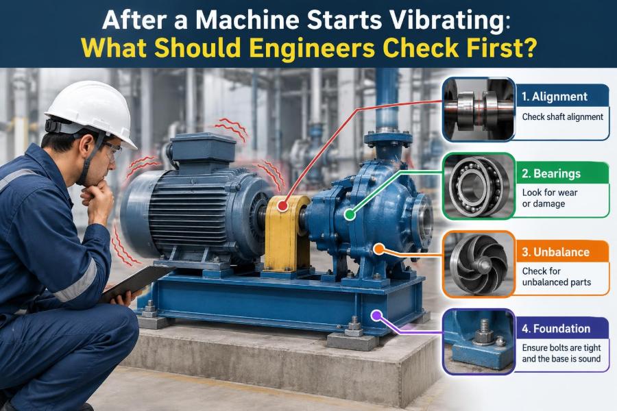
Unbalance occurs when a rotor’s mass center does not lie on its rotational centerline. As speed rises, the resulting centrifugal force rises rapidly, so an imbalance that seems minor at low speed can become significant at operating speed.
Common sources include deposited material on fan blades, erosion of an impeller, missing balance weights, damaged rotor parts, and uneven product accumulation. A clean fan becoming rough after handling sticky material is a practical example.
Before field balancing, confirm that the rotor is clean, secure, mechanically sound, and free from rubbing. Balancing a rotor with loose components or a changing deposit can mask the underlying issue and create an unreliable correction.
📐 Examine Alignment and Coupling Condition
Misalignment means connected shafts do not share the intended centerline and angular relationship during operation. It can increase bearing loads, coupling forces, seal wear, and vibration—especially after motor movement, base settling, thermal growth, or replacement work.
Check coupling condition, bolt tightness, element wear, hub fit, and shaft runout before assuming alignment is the only problem. Then assess alignment using an appropriate method for the machine and required accuracy.
Cold alignment is not always operating alignment. A hot pump, turbine-driven train, or machine with unequal support temperatures may move as it warms. Thermal growth targets should be based on equipment information and operating behavior, not guessed from a generic rule.
🧱 Inspect Soft Foot and the Machine Base
Soft foot exists when one or more machine feet do not sit flat on the base when the hold-down bolts are loosened. Tightening that bolt bends or twists the machine casing, changing alignment and loading bearings.
Check each foot systematically during alignment work, using safe lockout procedures. Corrective actions may include cleaning contact surfaces, removing burrs, improving shims, or addressing base distortion. Simply adding random shims can make the condition worse.
Also inspect the foundation, grout, soleplates, anchor bolts, and frame welds. A machine can be internally healthy but vibrate excessively because its support is no longer sufficiently stiff or securely connected.
🪛 Look for Mechanical Looseness
Mechanical looseness covers a wide range of conditions: loose bearing fits, worn pedestal interfaces, slack fasteners, cracked supports, excessive clearances, or components moving under load. It often produces harmonics of running speed, impacts, or unstable readings.
Not all looseness is visible. A bearing outer race can creep in its housing, a sleeve can fret on a shaft, or a structural joint can open only at high load. Changes in vibration direction or sudden differences between nearby measurement points may provide clues.
Tightening accessible bolts is sensible only when correct torque and the joint’s design requirements are known. Over-tightening, tightening a distorted structure, or ignoring the reason bolts loosened can introduce new problems.
🛢️ Evaluate Bearing Lubrication and Bearing Health
Rolling-element and fluid-film bearings have different failure mechanisms, but both depend on correct lubrication, fit, load, cleanliness, and operating temperature. A bearing problem may produce increased high-frequency energy, repetitive impacts, temperature change, or rough sound.
Check lubricant level, condition, contamination, grease type, relubrication practice, and evidence of overgreasing. More grease is not automatically better; excess grease can churn, heat, and damage seals.
Do not condemn a bearing solely from an overall vibration reading. Bearing diagnosis is stronger when vibration data, temperature, lubricant evidence, ultrasound where used, speed, and physical inspection all tell a consistent story.
🌡️ Check Temperature as a Supporting Signal
Temperature is rarely a stand-alone diagnosis, but it provides useful context. Compare bearing, housing, lubricant, motor, and process temperatures with prior operating values and with equivalent points on a similar machine where meaningful.
A rising bearing temperature can result from lubrication problems, excessive preload, misalignment, internal damage, or external heat transfer. Conversely, a vibration increase without a temperature change may still be serious, particularly in a rapidly developing balance or structural problem.
Infrared measurements require care. Surface emissivity, reflections, viewing angle, and painted or polished surfaces can affect readings. A permanently installed temperature sensor and a handheld infrared reading may not measure the same thing.
💧 Investigate Process-Induced Vibration in Pumps
For pumps, the hydraulic system is part of the machine. Restricted suction, entrained gas, inadequate liquid level, clogged strainers, unsuitable operating point, recirculation, and unstable control can all create vibration.
Cavitation involves vapor bubbles forming and collapsing as local pressure conditions change. It can create noise, vibration, loss of performance, and damage over time, but not every noisy pump is cavitating. Confirm process conditions rather than diagnosing by sound alone.
Review suction and discharge pressures, flow, valve positions, tank level, fluid temperature, and changes to line configuration. A mechanical repair will not permanently solve a vibration caused by an unsuitable hydraulic operating condition.
🌬️ Investigate Aerodynamic Effects in Fans and Compressors
Fans, blowers, and compressors can vibrate because of airflow disturbances rather than rotor defects. Blocked inlets, dirty filters, uneven inlet flow, damper position, duct restrictions, and operation near an unstable region can alter aerodynamic forces.
Blade-pass frequency—the rate at which blades pass a fixed point—may appear in vibration data. Its presence is normal to some degree; an unusual increase may indicate airflow changes, blade damage, fouling, or interaction with ductwork.
Check the system as well as the rotating assembly. A fan may be correctly balanced while the connected duct creates pulsation or forces it into an unfavorable operating condition.
⚡ Rule Out Electrical and Drive-System Contributors
Motor-related vibration can arise from electromagnetic forces, rotor bar issues, air-gap eccentricity, supply imbalance, or drive-control effects. Belt drives add belt condition, sheave alignment, tension, and pulley eccentricity to the investigation.
Electrical signatures can overlap mechanically generated frequencies, so collaboration between mechanical and electrical personnel is often necessary. Measure supply condition and review drive settings using appropriate procedures rather than treating every motor-side vibration as a bearing issue.
For a direct-coupled train, verify that the symptom follows the motor, driven machine, or combined operating condition before authorizing major work.
🏗️ Test for Resonance and Structural Flexibility
Resonance occurs when an excitation frequency approaches a structure’s natural frequency, allowing relatively small forcing to create large motion. Think of pushing a swing at its natural rhythm: modest pushes can build large movement.
Clues include vibration that peaks sharply over a narrow speed band, unusually high motion on a bracket or platform compared with a bearing housing, or large response after a small process or speed change. A speed sweep during controlled run-up or coast-down can be revealing.
Possible remedies include changing speed away from the critical range, increasing stiffness, improving support, modifying mass, or reducing the excitation force. Adding mass without analysis can shift the problem rather than solve it.
📏 Compare Motion Across the Whole Machine Train
Do not measure only the loudest bearing housing. Compare motor, coupling-end and opposite-end bearings, gearbox, driven machine, base, and connected structure. The pattern of motion helps show where energy originates and how it travels.
A high reading at one machine foot but not its bearing may indicate a support issue. Similar running-speed vibration on both machines may reflect alignment, common base flexibility, or coupled response. A localized high-frequency signal near one bearing suggests a different line of inquiry.
Document locations precisely so later measurements are repeatable. A photo-free written point description can still be effective: for example, “outboard pump bearing housing, vertical, directly above pedestal bolt.”
🧭 Use Phase Data When the Decision Requires It
Phase describes the timing relationship between cyclic vibration and a reference mark on the shaft, or between different measurement points. It is especially useful for evaluating unbalance, alignment behavior, structural motion, and resonance.
For example, phase changes rapidly through a resonance region, while a stable phase pattern at running speed may support a balance-related hypothesis. The interpretation depends on rotor type, support stiffness, sensor direction, and machine configuration.
Phase analysis is powerful but not magical. It requires a dependable reference, correct setup, and personnel who understand the limits of the method. Poor phase data can lead to confident but incorrect conclusions.
🔍 Distinguish Cause From Consequence
A damaged bearing may be the failure found during teardown, yet the initiating cause could have been misalignment, contamination, shaft current, inadequate lubrication, or base distortion. Replacing the bearing alone may restore operation briefly without preventing recurrence.
Likewise, loose bolts may be a cause of vibration or a consequence of a pre-existing vibration force. The repair should address the mechanism that repeatedly loads the joint, not just restore the fastener.
Good troubleshooting asks two questions: “What is vibrating?” and “What is creating the force or reducing the restraint?” The second question is where durable solutions are found.
🧪 Choose the Right Diagnostic Tool
Different faults reveal themselves through different tools. A practical investigation may combine vibration spectra, time waveforms, phase, tachometer data, temperature, lubricant analysis, ultrasound, electrical testing, process measurements, and visual inspection.
| Observed clue | Useful next check | Reason |
|---|---|---|
| Change follows shaft speed | Speed reference and spectrum | Relates peaks to rotational orders |
| Change follows flow or pressure | Process readings and valve positions | Tests hydraulic or aerodynamic forcing |
| Sharp peak at one speed | Controlled speed sweep and phase | Checks for resonance behavior |
| Heat with high-frequency vibration | Lubrication and bearing assessment | Builds evidence for bearing distress |
No instrument substitutes for a clear problem statement. Select the tool that can disprove or support the leading hypotheses.
🧰 Avoid the “Replace Parts Until It Stops” Approach
Replacing bearings, couplings, and motors without a diagnosis can be expensive and may introduce assembly errors. It also destroys evidence: a removed component may never be inspected properly, and the operating condition before repair may not be reproducible.
Parts replacement is justified when inspection identifies a defect or risk level demands intervention. But when practical, record baseline data first, preserve failed components for examination, and verify the repair afterward.
A useful repair includes a reason for the action, the evidence supporting it, and a plan to confirm whether vibration returned to an acceptable, stable condition.
📋 Build a Clear Troubleshooting Sequence
A repeatable sequence keeps teams from chasing every possible cause at once. The order should be adapted to site risk and machine criticality, but the following logic is widely useful:
- Protect people and decide whether continued operation is acceptable.
- Confirm the symptom with reliable measurements and operating context.
- Identify recent changes and inspect accessible external conditions.
- Compare locations, directions, speed, load, process state, and trend history.
- Test the most plausible hypotheses with targeted measurements.
- Correct the verified cause, then measure again under comparable conditions.
This sequence moves from low-cost, high-information checks toward more intrusive work.
🗂️ Document Findings So the Next Decision Is Better
Write down operating speed, load, process conditions, measurement points, sensor direction, instrument settings, observed sounds, temperatures, and actions taken. “High vibration at pump” is not enough to support a later comparison.
Good records also capture what was not found: no loose bolts, no temperature rise, no significant change with flow, or no rubbing marks. Negative evidence helps prevent the same dead ends from being repeated.
After repair, retain before-and-after data. That history improves future diagnostics and can reveal whether the correction addressed the cause or only reduced the symptom temporarily.
🤝 Involve Operations, Maintenance, and Reliability Early
Vibration troubleshooting crosses disciplines. Operators know when a sound changes or a control valve hunts. Maintenance teams know what was recently disturbed. Reliability personnel can connect trends and measurement patterns. Process and electrical specialists may hold the evidence that explains the forcing mechanism.
Sharing observations early prevents a narrow mechanical diagnosis from overlooking a process upset or electrical condition. It also makes recommended actions more workable because operating constraints are understood from the start.
The best investigation is not the one with the most data; it is the one that converts relevant data into a safe, testable decision.
🛑 Know When to Escalate
Some situations require specialist support or an immediate engineering review: rapidly rising vibration, shaft rubbing, repeated coupling or bearing failures, cracked foundations, suspected rotor damage, operation near a critical speed, or vibration on equipment with serious safety or production consequences.
High-speed, large, flexible, or critical machines may need advanced rotor-dynamics analysis, field balancing procedures, or vendor involvement. Do not apply a simple correction method to a complex machine train solely because it worked on a small fan.
Escalation is not a failure of troubleshooting. It is appropriate risk control when uncertainty, stored energy, or consequence exceeds what routine checks can resolve.
✅ The Core Principle: Verify Before You Correct
When a machine starts vibrating, the first check is not a single component. It is the operating and safety context: confirm the change, establish severity, and identify what changed around the machine before deciding where to intervene.
From there, work outward and inward: verify measurements, inspect supports and connections, relate vibration to speed and load, examine process effects, and use diagnostic tools to test—not merely decorate—a hypothesis. Treat the machine, drive, foundation, and process as one interacting system.
This approach is slower than guessing for the first few minutes, but faster over the life of the problem. It prevents repeated repairs, protects evidence, and produces explanations that can be applied to the next machine as well.
Effective vibration troubleshooting begins with a safe, verified understanding of the symptom and ends only when the force causing it—or the restraint failing to control it—has been addressed. ⚙️📈🛠️