
A workshop operator turns up a variable-frequency drive and expects the conveyor to move more product. A homeowner chooses a faster setting on a fan, expecting stronger cooling. A production engineer considers raising pump speed to meet a temporary demand spike.
The intuition is understandable: more revolutions per minute seem like they should mean more work. Sometimes they do. But machines do not respond to speed in one universal way, and a speed increase can deliver more output, waste energy, trigger vibration, overload a motor, or even reduce the useful result.
The reason is that “output” can mean several things: flow rate, torque, power, pressure, cutting rate, throughput, or product quality. Motor speed is only one variable in a larger mechanical and electrical system.
Understanding that system helps engineers choose the right speed rather than simply the highest available speed. It also explains why a machine that sounds more energetic is not necessarily doing better work.
⚙️ The Short Answer: It Depends on the Load
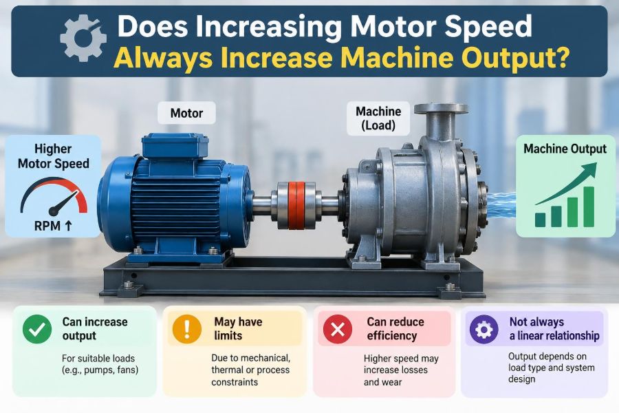
Increasing motor speed does not always increase useful machine output. The result depends primarily on how the driven load behaves as speed changes, along with the available motor torque, transmission ratio, control method, and operating limits.
A centrifugal pump, for example, usually delivers more flow when it spins faster. A screw conveyor may move more material only until filling, blockage, or motor torque becomes limiting. A cutting tool may produce parts faster at first, then generate excessive heat and poorer surface finish.
The useful question is therefore not “Can the motor spin faster?” but “What does the machine need, and can every part of the system safely support that operating point?”
🔄 Speed Means Rotational Motion per Unit Time
Motor speed is commonly stated in revolutions per minute, or rpm. It can also be expressed as angular speed, ω, in radians per second. Higher speed means the shaft completes more rotations in the same time.
Speed alone does not describe how hard a shaft can turn. A small motor can spin extremely fast while producing little turning force. Conversely, a geared drive can turn slowly while applying very large force at its output shaft.
This distinction becomes essential whenever a machine must start a heavy load, lift a weight, crush material, or push fluid against pressure.
🧲 Torque Is the Turning Force
Torque is the twisting effect available at a rotating shaft. It is measured in newton-metres in SI units. In everyday terms, torque is what lets a motor overcome resistance and accelerate a load.
Imagine using a wrench. Pulling harder increases torque; using a longer wrench also increases torque. A motor produces the equivalent turning action continuously, but its available torque changes with motor type, speed, supply conditions, and controller settings.
If required load torque exceeds motor torque, the system slows down, trips a protective device, stalls, or fails to start. Raising commanded speed does not solve that shortage by itself.
📐 Power Connects Torque and Speed
Mechanical rotational power is given by the relationship P = T × ω, where P is power, T is torque, and ω is angular speed. Power describes the rate at which mechanical work is delivered.
At constant torque, increasing speed increases mechanical power. At constant power, increasing speed requires torque to decrease. These two cases explain much of the confusion around motor performance.
A drive cannot provide unlimited torque and unlimited speed at the same time. Its rated current, voltage, thermal capacity, and mechanical design set a practical operating envelope.
🏷️ What “Machine Output” Actually Means
Before changing speed, define the output that matters. Different machines have different useful measures:
- A pump may be judged by flow and discharge pressure.
- A fan may be judged by air flow and static pressure.
- A conveyor may be judged by mass moved per hour.
- A mixer may be judged by blend uniformity, not simply rpm.
- A machine tool may be judged by parts per hour, accuracy, and tool life.
Increasing rpm may improve one measure while harming another. A mixer can circulate liquid more rapidly yet entrain air, damage shear-sensitive material, or create an unstable vortex.
🔌 Why Induction Motor Speed Is Not Fully Fixed
For an AC induction motor, synchronous speed is set by electrical supply frequency and motor pole count. A typical motor runs slightly below synchronous speed when loaded; this difference is called slip.
With a fixed-frequency supply, its operating speed changes only modestly with load. A variable-frequency drive, or VFD, changes supply frequency and allows a much wider controllable speed range.
A VFD is powerful, but it does not remove physical constraints. It can command higher speed only if the motor, drive, driven equipment, and safety systems are suitable for it.
🎚️ Constant-Torque and Constant-Power Regions
Many VFD-driven motors operate in a constant-torque region up to a base speed. The drive raises voltage roughly in proportion to frequency, maintaining magnetic flux and allowing rated torque within current limits.
Above base speed, the available voltage is often already at its maximum. The motor then enters field weakening, where available torque falls as speed rises. The system may still provide approximately constant power over a limited range.
| Operating region | Typical capability | Useful applications |
|---|---|---|
| Below base speed | Approximately constant torque | Conveyors, extruders, hoists within approved limits |
| Above base speed | Torque decreases as speed increases | Spindles, some machine tools, approved fan duties |
This is why “just run it faster” may fail for a high-torque application.
🪨 Constant-Torque Loads Respond Differently
A constant-torque load requires roughly the same torque across its normal speed range. Conveyors, positive-displacement pumps, screw feeders, and many mixers often approximate this behavior, although real systems can vary.
If torque remains constant, power demand rises nearly in direct proportion to speed. Doubling speed roughly doubles required power, assuming the process and losses remain similar.
That can increase throughput, but only if material handling, bearings, gearbox ratings, and motor power capacity are adequate. A conveyor moving twice as fast may also create loading, spillage, or sorting problems downstream.
🌬️ Fans and Pumps Follow Affinity Laws
Centrifugal fans and pumps are common examples of variable-torque loads. For geometrically similar operation with the same fluid, their approximate affinity relationships are highly useful.
- Flow rate changes roughly in proportion to speed.
- Pressure or head changes roughly with the square of speed.
- Power demand changes roughly with the cube of speed.
The cubic relationship is the caution. A modest increase in fan or pump speed can require a much larger power increase. These are approximations, not guarantees: system resistance, cavitation, impeller geometry, and control arrangements affect real performance.
💧 More Pump Speed Can Produce Less Useful Flow
A centrifugal pump must operate where its pump curve intersects the system curve. Raising speed shifts the pump curve, but it does not guarantee a proportional increase in delivered flow.
Pipe friction rises as flow increases, valves may impose losses, and a restrictive system can absorb much of the extra head. In some conditions, insufficient suction pressure causes cavitation: vapor bubbles form and collapse, producing noise, vibration, reduced performance, and possible damage.
For a pump, useful output is not simply shaft rpm. It is stable flow and pressure delivered at an acceptable efficiency and within suction, seal, and motor limits.
🌀 Fan Speed Changes Pressure, Noise, and Comfort
Increasing fan speed generally raises air flow, but the outcome depends on duct resistance and the fan’s operating point. A poorly designed duct system may gain little useful air delivery while consuming considerably more power.
Noise also rises with speed and turbulence. In ventilation systems, excessive velocity can create drafts, whistle through grilles, and make a room less comfortable even if measured airflow is higher.
The best fan setting is often the lowest speed that satisfies airflow, pressure, temperature, or contamination-control requirements.
🚚 Conveyor Throughput Has Bottlenecks
A faster belt can increase theoretical conveyor capacity. Yet actual throughput is often constrained by how quickly material is loaded, how evenly it is distributed, and what happens at transfer points.
At higher speed, packages can slide, bulk solids can bounce, and gaps between items can disappear. The receiving machine may become the bottleneck, causing accumulation or jams.
Speed adjustment should be coordinated across the line. A sensor, accumulation zone, or control logic may add more value than increasing one conveyor’s motor speed.
🛠️ Machine Tools Need the Right Cutting Speed
For drilling, milling, turning, and grinding, spindle speed affects cutting speed at the tool edge. A faster spindle can shorten cycle time, but only when feed rate, depth of cut, tool material, coolant, and workpiece material are matched.
Too low a speed may rub instead of cut cleanly. Too high a speed can accelerate tool wear, generate heat, cause chatter, and reduce dimensional accuracy. The best setting comes from process parameters, not a universal “faster is better” rule.
In this context, useful output includes part quality and predictable tool life as well as parts produced per hour.
⚖️ Gearboxes Trade Speed for Torque
A gearbox changes the relationship between motor speed and machine speed. A speed reduction lowers output rpm and multiplies available output torque, subject to efficiency losses.
For example, a motor may spin efficiently at high rpm while a hoist drum needs lower speed and higher torque. The gearbox creates a compatible operating point between them.
Changing motor speed without considering the gear ratio can push either side of the transmission outside its intended range. Gear teeth, lubrication, bearings, and shaft critical speeds all impose limits.
📈 Acceleration Requires Extra Torque
Steady operation is only part of the story. To increase speed, a motor must accelerate its own rotor, couplings, gears, and the driven load. The required accelerating torque depends on rotational inertia and desired acceleration rate.
A large flywheel or loaded conveyor may run comfortably at a target speed but require excessive current to reach it too quickly. VFD acceleration ramps help limit current and mechanical shock.
Fast acceleration can be useful in indexing systems and dynamic machinery, but it must be designed rather than assumed. Repeated starts also add thermal stress to motors and drives.
🌡️ Motor Heating Often Sets the Real Limit
Electrical losses in motor windings create heat, and bearing, fan, and iron losses also contribute. A motor can tolerate only a defined thermal condition based on its insulation system, cooling method, ambient temperature, and duty cycle.
At low speed, a self-cooled motor’s shaft-mounted fan moves less air. It may therefore overheat while producing rated torque at low rpm unless separately cooled or specifically rated for that duty.
At high speed, windage and other losses can rise. The safe speed range must come from motor and drive documentation, not from an assumption based solely on rated power.
🧯 Overspeed Creates Mechanical Risks
Rotating components store kinetic energy, and that energy rises strongly with speed. Overspeed increases stress in shafts, impellers, rotors, couplings, belts, and grinding wheels.
Bearings may exceed their speed capability, lubrication can become inadequate, and seals may fail. An impeller or wheel has a maximum permissible speed for structural reasons; exceeding it is not a normal productivity adjustment.
Protective measures can include drive speed limits, independent overspeed trips where appropriate, guards, proper balancing, and inspection of critical rotating parts.
📳 Vibration and Resonance Can Appear Suddenly
Every rotating system has natural frequencies. When running speed or a harmonic approaches one of them, vibration can rise sharply. This condition is known as resonance or a critical speed.
A machine may operate smoothly at 1,400 rpm and 1,800 rpm but vibrate severely between them. Passing quickly through a critical speed may be acceptable for some designs; continuous operation there may not be.
Increased vibration is not merely a comfort issue. It can loosen fasteners, damage bearings, fatigue supports, and distort process results. Vibration measurements are valuable before approving a higher-speed setting.
⚡ The Electrical Supply May Be the Constraint
A motor’s nameplate current, the VFD current rating, cable capacity, upstream protection, and supply quality all affect what speed and load can be sustained. High torque demand often means high current, especially during acceleration.
Running above base speed may also require attention to voltage limits and field weakening. A controller may reach its current or voltage limit before the requested process output is achieved.
Electrical protection should not be defeated to force production. A trip is often evidence of an incorrect operating point, excessive load, poor tuning, or a developing mechanical fault.
📉 Efficiency Does Not Stay Constant
Motors, gearboxes, pumps, and fans each have efficiency ranges. Operating far below or above the intended duty point can increase losses and energy cost per unit of useful output.
For centrifugal systems, reducing speed with a VFD can be particularly effective when demand is lower, because power demand falls rapidly with speed. However, a VFD is not automatically the best solution in every installation; duty cycle, control needs, and equipment compatibility matter.
Energy performance should be evaluated using measured flow, pressure, production rate, and electrical input—not rpm alone.
🧪 Process Quality Can Be the Hidden Output
Many processes have a speed range rather than one ideal maximum. In mixing, greater tip speed can improve dispersion but may shear particles, emulsions, fibers, or biological material. In extrusion, higher screw speed can raise output but alter temperature, pressure, and residence time.
In packaging, faster motion can reduce dwell time for sealing or increase product damage. In winding operations, speed affects tension and alignment.
A production target that ignores quality creates rework, scrap, and downtime. The truly useful output is acceptable product made reliably.
🧭 Read the Machine Curve, Not Just the Nameplate
A motor nameplate provides rated electrical and mechanical information, but it does not describe the complete driven system. Performance curves, torque-speed curves, pump curves, fan curves, gearbox data, and manufacturer speed limits provide the needed context.
For a pump or fan, plot the expected operating point. For a conveyor or mixer, estimate required torque throughout starting, acceleration, and steady operation. For a spindle, use approved tooling and cutting data.
When information is missing, a controlled test with measurement and suitable safeguards is more defensible than guessing.
📏 Measure the Output That Matters
Speed is easy to display, so it is tempting to treat it as performance. Better decisions use measurements tied to the process.
- Measure flow and pressure for fluid systems.
- Measure current, power, and temperature for the drive system.
- Measure throughput, rejects, and cycle time for production equipment.
- Measure vibration and bearing condition for rotating machinery.
- Measure quality characteristics that customers or downstream processes actually require.
These measurements reveal whether an rpm increase created useful capacity or merely moved the constraint elsewhere.
🧑🔧 A Practical Speed-Change Checklist
Before raising motor speed, treat the change as an engineering modification, even if it is made through a familiar drive keypad.
- Define the desired process outcome and how it will be measured.
- Identify the load type and estimate torque and power demand.
- Check motor, VFD, gearbox, coupling, belt, bearing, and driven-machine speed ratings.
- Review starting, acceleration, braking, and emergency-stop behavior.
- Check vibration, cooling, lubrication, suction conditions, and guarding.
- Increase speed in controlled steps while recording relevant measurements.
- Document the approved operating range and update control limits.
For safety-critical or high-energy equipment, involve qualified engineers and follow site procedures and manufacturer instructions.
🚫 Common Mistakes When Chasing Higher RPM
One frequent mistake is assuming rated motor power is available at every speed. Another is looking only at steady-state current and ignoring acceleration, heating, or vibration.
Operators may also increase speed to compensate for a process restriction—a clogged filter, worn pump impeller, undersized duct, poor feeder arrangement, or blunt cutting tool. The faster setting can mask the root cause while worsening damage or energy use.
A third mistake is treating a VFD as a universal upgrade. It gives control, not unlimited machine capability.
🔧 Better Alternatives to Increasing Speed
When output is low, the best answer may be to reduce resistance or improve the process rather than spin the motor faster. Cleaning a filter, opening an appropriate valve, correcting belt tension, improving material feeding, or repairing a worn component can restore performance.
Other options include selecting a more suitable impeller, changing a gear ratio, installing a larger machine designed for the duty, or adding parallel equipment for variable demand.
These choices require capital or downtime, but they can provide a safer and more efficient solution than persistent overspeed operation.
🧠 A Simple Decision Framework
Ask four questions in sequence: What output must increase? What mechanism currently limits it? What happens to torque, power, and process quality if speed rises? Can the entire system safely operate there?
If the limit is motor speed and the load is compatible, a speed increase may be effective. If the limit is pressure loss, thermal capacity, material supply, vibration, or a downstream station, higher rpm may offer little benefit.
This framework prevents a control setting from being mistaken for a complete engineering solution.
✅ The Core Principle: Match Speed to the Duty
Motor speed is a valuable control variable, but it is only one part of machine performance. Torque determines whether resistance can be overcome; power determines the rate of work; the load characteristic determines how demand changes; and mechanical, thermal, electrical, and process limits define what is acceptable.
The best operating speed is the one that meets the required output with stable operation, suitable quality, reasonable energy use, and adequate safety margin. Sometimes that is faster. Sometimes it is slower, or it requires a different mechanical or process change entirely.
Increasing motor speed increases useful output only when the load, machine, power system, and process are all designed to benefit from that increase.
More rpm is not automatically more performance; the right rpm is the speed that delivers the required work without creating a new limit somewhere else. ⚙️📈🛠️