
A car climbs a hill in a low gear. A workshop drill bites into steel. A ceiling fan accelerates after its switch is pressed. In each case, something is turning, resisting, and transferring energy.
It is tempting to judge the machine by a single number: torque for a truck, revolutions per minute for a motor, or kilowatts for an electric tool. But no one of these quantities tells the whole story.
Mechanical power connects them. It tells us how quickly a rotating shaft can do useful work, and it explains why a high-torque machine can still be slow, while a fast-spinning machine may deliver surprisingly little output.
For engineers, technicians, and anyone choosing or operating machinery, the relationship is practical rather than abstract. It affects gear selection, motor sizing, acceleration, heating, efficiency, and whether a machine can complete its intended job.
⚙️ Mechanical Power Is a Rate of Doing Work
Power is the rate at which energy is transferred or work is done. A machine may be capable of applying a large force, but if it applies that force very slowly, its power can be modest.
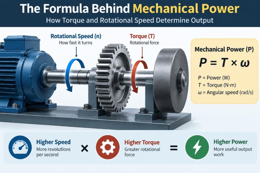
For linear motion, power equals force multiplied by velocity. For rotation, the equivalent quantities are torque and angular speed. This is why a rotating motor, gearbox, turbine, or engine is commonly described by its shaft power.
In SI units, power is measured in watts (W), where one watt is one joule per second. Larger machines are often rated in kilowatts (kW) or megawatts (MW).
🔩 Torque Is the Twisting Effect
Torque is the turning effect of a force about an axis. Pushing a door near its handle produces more torque than pushing near the hinge, even if the applied force is the same.
Mathematically, torque is force multiplied by perpendicular distance from the axis. Its SI unit is the newton-metre (N·m). That unit resembles the joule dimensionally, but torque is not energy: it describes a rotational tendency.
A shaft transmitting torque is like a person turning a wrench. The amount of twist available matters, especially when overcoming a heavy load, friction, or starting resistance.
🌀 Rotational Speed Describes How Fast a Shaft Turns
Rotational speed is often stated in revolutions per minute, or rpm. It is intuitive: 1,500 rpm means the shaft completes 1,500 full turns each minute.
The power equation, however, uses angular velocity, usually represented by the Greek letter ω (omega) and measured in radians per second. One complete revolution is 2π radians.
Speed is not torque. A small fan motor may rotate rapidly with little resistance, while a large winch motor turns slowly but exerts substantial torque.
📐 The Core Formula for Rotating Machinery
The fundamental relationship is:
P = T × ωHere, P is mechanical power in watts, T is torque in newton-metres, and ω is angular velocity in radians per second.
This formula says that power rises when torque rises at a given speed, or when speed rises at a given torque. It does not say that either quantity can increase without limit; real machines face electrical, thermal, structural, and traction constraints.
🔄 Converting RPM to Angular Velocity
Because rpm is common in specifications, engineers often convert it before using the SI form of the equation:
ω = 2πN / 60In this expression, N is speed in rpm. Substituting it into the power equation gives a useful practical form:
P = 2πTN / 60Use consistent units. Torque must be in N·m and speed in rpm if the result is intended to be watts through this version of the equation.
🧮 A Worked Power Calculation
Consider a hypothetical motor delivering 40 N·m of torque at 1,200 rpm. Its angular velocity is approximately 125.7 rad/s.
Multiplying torque by angular velocity gives about 5,027 W, or approximately 5.0 kW. The calculation is:
P = 40 × (2π × 1200 / 60) ≈ 5,027 WThis result is the mechanical power at the shaft under those stated conditions. It is not automatically the electrical power drawn from the supply, because the motor and its drive have losses.
📊 A Quick Reference for Common Units
Unit conversions are a frequent source of avoidable errors. The following relationships help keep calculations traceable.
| Quantity | Common form | Useful relationship |
|---|---|---|
| Power | kilowatt | 1 kW = 1,000 W |
| Rotational speed | rpm | ω = 2πN / 60 |
| Torque | N·m | Use directly with rad/s for watts |
| Horsepower | hp | Its exact watt equivalent depends on the horsepower convention used |
When horsepower appears in older documentation, confirm whether it refers to mechanical, metric, or another convention before making a precise conversion.
🚗 Why Torque Alone Does Not Define Performance
A specification that advertises high torque can be meaningful, but it is incomplete. Torque at nearly zero speed can help start a load, yet power at zero speed is zero because there is no rotational motion.
That distinction matters in vehicles. An engine may generate strong low-speed torque, but vehicle performance also depends on engine speed, gear ratios, tire radius, mass, available traction, and the operating range over which torque is maintained.
Torque describes twisting capability at a moment. Power describes how rapidly that capability can sustain energy transfer.
🏎️ Why Speed Alone Is Not Enough
High rpm does not guarantee high power either. A lightly loaded spindle can rotate extremely fast while transmitting little torque and therefore little mechanical power.
Imagine turning an unloaded screwdriver quickly in the air. Your hand may make many rotations, but it is doing little useful mechanical work on an external load. Press the screwdriver into a resistant screw and torque becomes necessary.
A practical power rating always needs both sides of the relationship: turning effort and turning rate.
⚖️ The Torque–Speed Trade-Off
Many motors and engines cannot provide their maximum torque at every speed. Their torque-speed curves reflect electromagnetic behavior, fuel and air flow, control strategy, friction, cooling, and mechanical limitations.
As speed rises, some machines lose available torque. Power may still increase if speed rises faster than torque falls. Eventually, torque reduction or a speed limit causes power to peak and then decline.
Reading the curve, rather than relying on a single headline value, is essential when matching a prime mover to a load.
📈 Reading a Power Curve and Torque Curve
A torque curve plots available torque against speed. A power curve plots calculated or measured power against speed. Because power equals torque times angular velocity, their shapes are related but not identical.
At a particular speed, a torque peak does not necessarily coincide with a power peak. Power often peaks later, provided enough torque remains as rpm increases.
For a machine designer, the useful question is not simply “Where is the peak?” It is “What torque and power are available throughout the actual operating range?”
⚡ Electric Motors Have a Distinct Operating Pattern
Many electric motor-drive systems can deliver high torque from low speed. With suitable control, they commonly operate in a constant-torque region up to a base speed.
Above that speed, voltage limits may require field weakening or a similar control approach. Torque then tends to fall as speed rises, creating an approximate constant-power region over part of the range.
Actual behavior depends on motor type, inverter capability, thermal limits, and control settings. A catalog curve should be used rather than assuming every electric motor follows an identical pattern.
🔥 Internal-Combustion Engines Build Power Differently
An internal-combustion engine produces torque through repeated combustion events. Its torque depends on factors such as air charge, fuel delivery, valve timing, turbocharging, combustion quality, and friction.
At low speed, the engine may not move enough air or operate in its most favorable conditions. At very high speed, filling losses, friction, and limited combustion time can reduce torque.
Its power band is therefore finite. Transmissions help keep the engine near a speed where it can provide suitable power for the requested vehicle output.
⚙️ Gearboxes Exchange Speed for Torque
A gearbox changes the relationship between shaft torque and shaft speed. A reduction gear lowers output speed and raises output torque, while a speed-increasing gear does the reverse.
In an ideal gearbox, power would remain unchanged: less speed is exchanged for more torque. In reality, gears, bearings, seals, and lubricant agitation create losses, so output power is somewhat lower than input power.
This is why gears do not “create” power. They make existing power more useful for a particular task.
🚲 A Bicycle Makes the Gear Principle Visible
On a steep hill, selecting a lower bicycle gear lets the rider apply greater torque at the rear wheel for a given pedal force. The wheel turns more slowly for each pedal revolution, but climbing becomes manageable.
On level ground, a higher gear can increase road speed when the rider has enough power to keep turning the pedals. The rider’s body supplies the energy; the drivetrain trades speed and torque to suit conditions.
The same principle appears in cranes, conveyors, vehicle transmissions, machine tools, and robotic joints.
🏗️ Loads Demand Different Torque Behaviors
Mechanical loads are not all alike. Their required torque often changes differently with speed, which strongly affects motor selection.
- Constant-torque loads: conveyors, mixers, and positive-displacement pumps often need similar torque over much of their speed range.
- Variable-torque loads: centrifugal fans and pumps generally require torque that rises strongly with speed.
- Constant-power loads: some winding, machining, and traction applications may be controlled to operate near a power limit over a range.
A motor that works well for a conveyor may be a poor direct replacement for a fan drive, even if their nominal power ratings match.
🌬️ Fans and Pumps Can Surprise Designers
For many centrifugal fans and pumps, the required power rises approximately with the cube of rotational speed under comparable conditions. A modest increase in speed can therefore demand a much larger increase in power.
This behavior explains why variable-speed drives can be valuable in suitable ventilation and pumping systems. Reducing speed may sharply reduce the mechanical power required.
These relationships are application-dependent. Fluid system resistance, impeller geometry, and operating point must be considered before applying simplified scaling rules.
🧲 Starting Torque Is Not Starting Power
At standstill, angular speed is zero. Therefore shaft power is zero even if the motor is applying substantial torque.
That torque is still crucial because it accelerates inertia and overcomes static friction, gravity, or process resistance. As the shaft begins to rotate, mechanical power rises.
This distinction prevents a common misunderstanding: a motor can be heavily loaded electrically at startup while its mechanical shaft power is initially zero.
🎯 Acceleration Requires More Than Steady-State Power
A rotating system stores kinetic energy in its rotating parts. Accelerating a heavy flywheel, large fan, or machine spindle requires additional torque beyond that needed to maintain steady speed.
The required accelerating torque depends on rotational inertia and angular acceleration. Once target speed is reached, that extra acceleration torque can fall away, unless the speed continues to change.
Motor sizing must therefore consider the duty cycle: starts per hour, acceleration time, load inertia, and allowable temperature rise, not just steady running output.
🧱 Friction, Gravity, and Process Resistance Consume Output
Available shaft power is used to overcome the load. That load may include bearing friction, belt losses, rolling resistance, fluid drag, cutting forces, gravity while lifting, or material being processed.
A hoist is a clear example. Raising a mass needs torque at the drum, while lifting it faster needs more power. The same load lifted twice as fast requires roughly twice the ideal lifting power.
Understanding where the power goes helps engineers identify whether a problem is a motor limitation, excessive friction, poor gearing, or an unexpectedly demanding process.
🔌 Input Power Is Not the Same as Shaft Power
Electrical input power, fuel energy input, and mechanical shaft output are different quantities. A motor converts electrical energy to shaft power with losses in windings, magnetic materials, bearings, cooling fans, and electronics.
Efficiency is output power divided by input power. No real conversion system is perfectly efficient, so a motor delivering a stated shaft output generally draws more input power than that output.
Efficiency also varies with speed, load, temperature, and design. A nameplate value is useful, but it does not replace checking the manufacturer’s performance data for the intended operating point.
🌡️ Thermal Limits Often Set the Real Boundary
A motor may briefly produce torque above its continuous rating, but heat accumulation can limit how long it can do so. Copper losses rise with current, and insufficient cooling can damage insulation, magnets, lubricant, or electronic components.
At low speed, a self-cooled motor’s fan may move less air. High torque at low rpm can therefore become thermally demanding even when calculated mechanical power is not especially large.
Continuous torque, peak torque, overload duration, ambient temperature, enclosure, and cooling method all belong in a serious selection process.
🛠️ Measuring Torque and Speed in Practice
Torque can be measured with a rotary torque transducer, reaction torque arrangement, or indirectly estimated from motor current and a calibrated motor model. Speed can be measured with an encoder, tachometer, resolver, or sensorless control estimate.
Once torque and speed are known at the same shaft and time, power can be calculated. This is valuable for commissioning equipment, diagnosing overloads, and validating a design.
Measurements need context. Torsional vibration, transient loads, sensor accuracy, sampling rate, and where the sensor is placed can all affect the result.
📍 Measure at the Correct Shaft Location
Power changes as it passes through a drivetrain because every component has losses. Measuring torque before a gearbox answers a different question from measuring it at the output drum or wheel.
Likewise, a speed sensor on a motor shaft cannot be used directly with output-shaft torque unless the gear ratio is accounted for. Mixing locations produces calculations that look plausible but are physically wrong.
Label measurements clearly: motor shaft, gearbox input, gearbox output, or driven machine shaft.
⚠️ Common Calculation Mistakes
Most errors are simple rather than advanced. They can nevertheless lead to an undersized motor, an unrealistic efficiency claim, or a misleading performance comparison.
- Using rpm directly in
P = Tωwithout converting it to rad/s. - Mixing torque units, such as N·m and lb·ft, without conversion.
- Confusing a motor’s peak torque with its continuous torque rating.
- Assuming gearbox output power equals input power.
- Using torque from one shaft and speed from another.
- Ignoring acceleration, duty cycle, or a load’s changing torque requirement.
A dimensional check is a useful safeguard: N·m multiplied by rad/s gives watts, since radians are dimensionless in SI analysis.
🧾 A Practical Sizing Workflow
Start with the load, not the motor catalog. Define what the machine must move, how fast it must move, and how often it must start, stop, or reverse.
- Determine load torque across the required speed range.
- Add friction, gravity, process resistance, and acceleration torque where applicable.
- Calculate required mechanical power at relevant operating points.
- Select gearing that places the motor in a suitable speed and torque range.
- Account for drivetrain efficiency and service conditions.
- Check continuous thermal capability, peak torque, controller limits, and safety margins.
This workflow is more reliable than choosing a motor solely by a kW rating or a single maximum torque figure.
🔧 Matching the Machine to Its Duty Cycle
A packaging machine that makes rapid, repeated index moves needs a different drive strategy from a pump that runs steadily for months. Their average power may be similar while their peak torque and thermal demands differ greatly.
Intermittent duty can permit short overloads if cooling time is available. Continuous duty requires sustained operation within ratings. Reversing loads can add fatigue and control demands that a steady unidirectional load does not create.
Define the time history of speed and torque whenever the application is dynamic.
🧠 Power Is Also a Control Problem
Modern drives do more than energize motors. They regulate torque, speed, acceleration, and sometimes power to protect equipment or achieve a process target.
A torque limit can protect a gearbox or tooling. A speed limit can reduce overspeed risk. A power limit may prevent an electrical supply, battery, or engine from being overloaded.
These limits can interact. If a drive reaches its torque limit, it may not accelerate as commanded; if it reaches its power limit at higher speed, available torque must decrease.
🛡️ Safety and Mechanical Limits Still Matter
Power calculations do not replace mechanical design checks. Shafts, couplings, keys, gears, belts, fasteners, and bearings must withstand expected torque, shock loading, fatigue, and misalignment.
High-speed rotating equipment also brings containment, balance, guarding, and overspeed concerns. A component that transmits acceptable torque at low speed may not be safe at a much higher rotational speed.
Use applicable design standards, manufacturer limits, and qualified engineering review for safety-critical or high-consequence equipment.
🔍 Choosing Between More Torque and More Speed
If a machine needs more output, the answer is not automatically a larger motor. A different gear ratio may provide the required output torque, but it will change output speed and may affect acceleration or cycle time.
Conversely, increasing speed can raise available power at a given torque, but it may exceed bearing, noise, balance, or process limits. The correct choice depends on the load curve and the job to be done.
The best design matches torque, speed, and power at the driven machine—not merely at the motor nameplate.
🧭 The Central Principle to Remember
Rotational mechanical power comes from two inseparable ingredients: torque and angular speed. Torque gives the turning effort; speed gives the rate at which that effort is applied.
The concise equation P = Tω provides a powerful way to interpret motor curves, compare drivetrains, calculate shaft output, and understand why gears alter torque and speed without creating energy.
Use it with real operating conditions in mind: efficiency losses, changing loads, acceleration, thermal limits, and component strength determine whether a calculated output can actually be delivered reliably.
A rotating machine produces useful mechanical power only when it combines sufficient torque with sufficient rotational speed for the load at hand. Once that relationship is clear, many choices in motors, engines, gearboxes, and driven equipment become far easier to reason through. ⚙️🔄📐