A Centrifugal pump is a mechanical machine that pumps the fluids by converting the mechanical power (rotational energy) into the pressure energy of the fluid flow. This mechanical power generally supplies by the electric motor or engine. A centrifugal pump uses a centrifugal force to pump the fluids. Therefore, it is known as a centrifugal pump.
It is a simplest type of hydraulic equipment that uses in a wide variety of industries and in many everyday appliances to move fluids from low to high-pressure areas. It uses an impeller to pump the fluid or water from one location to other. In 1475, engineer Francesco Di Giorgio Martini designed a centrifugal pump as a mud lifter device.
The actual centrifugal pump was only discovered in the 17th century. Next, Denis Papin designed a centrifugal pump with straight blades. British discoverer John Appold invented a curve vane centrifugal pump in 1851.
These types of dynamic pumps mostly use in the food and chemical industries to efficiently pump viscous liquids. These pumps are cheaper than positive displacement pumps. In simple words, it is a brilliant pump that can work efficiently in a different application.
Centrifugal pumps are very common all over the world industries. The main reason for their popularity is that these pumps have no power loss due to friction. This dynamic pump has a simple design and very easy to control. They don’t have leakage and heat transfer problems. This is the reason they get preference over the positive displacement pump.
Working Principle of Centrifugal Pump
The centrifugal pump working principle is according to the basic principle of the angular momentum which states that the change in the angular momentum of a revolving element is equivalent to the applied force.
It represents, when a specific quantity of the fluid rotates due to an external force (force provide by an electrical motor or a turbine), a centrifugal force appears on the fluid, which further converts the fluid speed into pressure. Some part of this energy converts into the fluids’ kinetic energy.
Centrifugal Pump Working
The working of a centrifugal pump is almost similar to the centrifugal compressor but there is only a difference of working fluid. A centrifugal pump works in the following way:

- First of all, mechanical power is provided to the pump impeller by an electric motor or engine. The impeller directly connects with the electric motor through a shaft and reciprocates with the motion of the motor shaft.
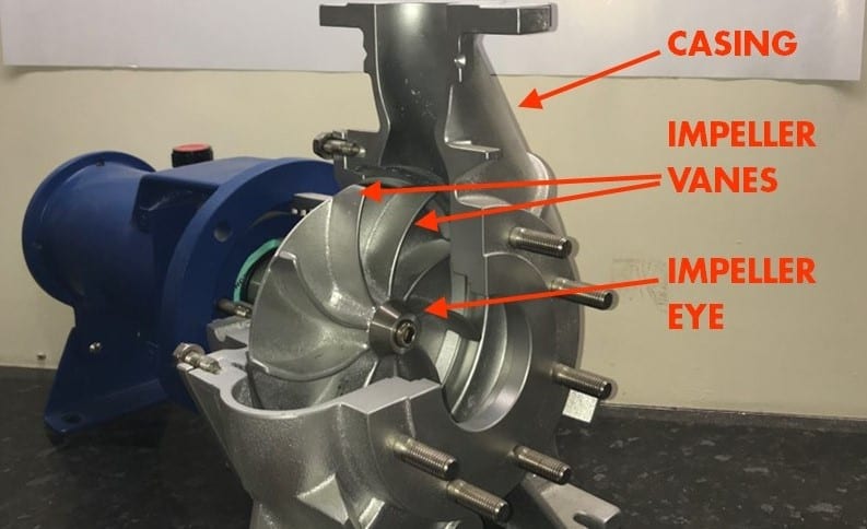
- When the impeller starts rotating, a vacuum starts generating inside the impeller’s eye. Due to this vacuum, the water starts to enter inside the eye in the axial direction.
- As the water enters in the eye, the water strikes the blades of the impeller. The impeller rotates the water radially and axially outward with the help of centrifugal force. This impeller continues this movement of water until it passes through all its components.
- The impeller blades convert the kinetic energy of the water into its speed and increase the water speed.
- After passing through the impeller, the water enters into the diffuser area. This diffuser slows down the water by reducing its speed. It converts the speed of the water into pressure energy. After increasing the desired pressure, the water discharges through the pump outlet and transfer it into the desire position.
In this way, a centrifugal pump increases the pressure and pumps the different fluids.
In simple words, in a centrifugal pump, fluid or water rises to a certain height due to the centrifugal force acting on these fluids or water. Therefore, this pump knows as a centrifugal pump. And this a complete working principle of the centrifugal pump.
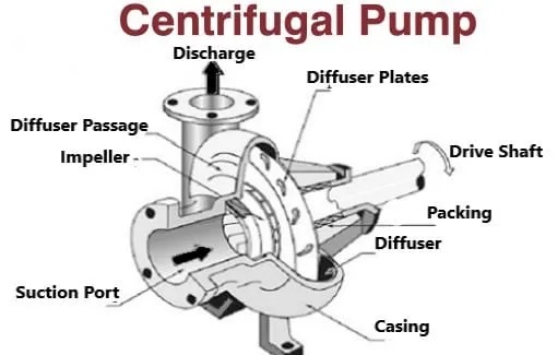
Parts of Centrifugal Pump
The major components of the centrifugal pump are given below in detail:
- Casing
- Suction pipe
- Diffuser
- Delivery Pipe
- Impeller

1) Casing
The casing is a narrow air passage around the impeller. The casing includes in the major components of the centrifugal pump.
It designs in such a shape that it converts the kinetic energy of the fluid discharged by the impeller outlet into pressure energy before the fluid exits the casing and goes into the discharge pipe. There are following three main types of the centrifugal pump casing:
(a) Volute Casing:
It has a spiral-type design. The volute casing has a gradual increase in the flow area. As the flow area increases, the speed slows, and the pressure of the fluid increases. This type of casing is given in the above diagram.
(b) Vortex Casing:
The vortex housing introduces a circular cavity between the casing and impeller. It uses to avoid energy loss due to the creation of swirls. These types of casings have high efficiency than volute casings.
(c) Guide Blades Casing:
In this type of casing, the runner surrounds with the help of a different number of guide blades. These blades attach around a ring that is known as a diffuser.
The guide blades are designed in such a way that they don’t affect the water exiting the impeller as it enters the diffuser. As the area of these blades increase, the water velocity reduces and its pressure energy increase. Mostly, the casing remains concentric with the impeller.
2) Suction Pipe
The bottom side of the suction pipe immerses in the water to that we want to lift while other side connects with the inlet of the centrifugal pump.
This part of the centrifugal pump has a foot and strainer valve at its bottom end. The role of these valves is to remove debris like sands, leaves, and allow the water to flow upwards.
3) Rotating Parts
These parts of the centrifugal pump consisting of an impeller and a shaft:
i) Impeller:
The impeller includes in the most important components of the centrifugal pump. It increases the pressure and speed of the fluid. The impeller gives centrifugal acceleration to the fluid. It further divides into the below-given parts.
a) Open impeller:
The impeller has no crown and bottom plate. The open impeller can be used to remove liquids that contain solid particles, like water having paper pulp or sand, e.tc.
b) Close impeller:
These impellers have cover plates on both sides of the blades. The close impeller uses to obtain pure water.
c) Semi-open impeller:
This type of impeller has only a base plate, but it doesn’t have a crown plate. These impellers are for the fluids having loading debris.
ii) Shaft:
The shaft uses to turn the impeller. It designs to transmit the torque generated when starting and operating the impeller and other revolving parts.
iii) Shaft Sleeve:
The sleeve prevents the shaft of the pump by leakage and corrosion. One end of the sleeve must be sealed.
4) Delivery Pipe
This part of the centrifugal pump uses to lift fluid to the required area. One end of the delivery pipe connects with the outlet of the pump, and the other end connects with the height where we want to transfer fluid.