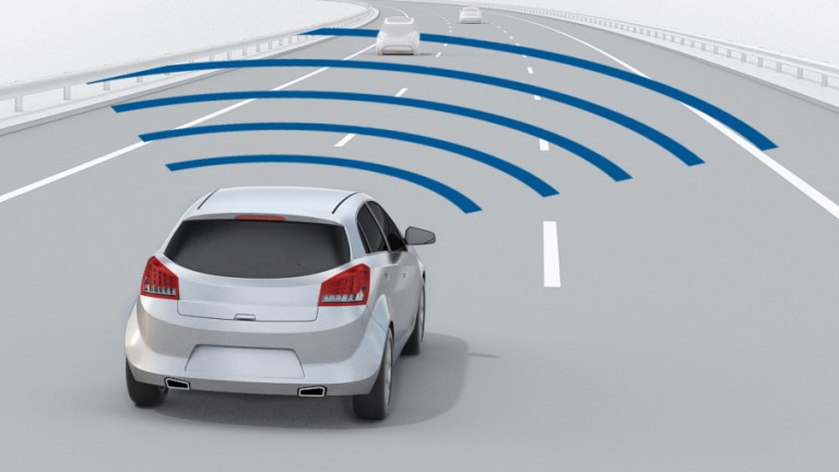
Adaptive Cruise Control (ACC) is an automotive feature that allows a vehicle’s cruise control system to adapt the vehicle speed to the environment. A radar system attached to the front of the vehicle is used to detect whether slower moving vehicles are in the ACC vehicle path. If a slower moving vehicle is detected, the ACC system will slow the vehicle down and control the clearance, or time gap, between the ACC vehicle and the forward vehicle. If the system detects that the forward vehicle is no longer in the ACC vehicle path, the ACC system will accelerate the back to its set cruise control speed. This operation allows the ACC vehicle to autonomously slow down and speed up is controlled is via engine throttle control and limited brake operation.
HOW DOES IT WORK?
The radar headway sensor sends information to a digital signal processor, which in turn translates the speed and distance information for a longitudinal controller. The result? If the lead vehicle slows down, or if another object is detected, the system sends a signal to the engine or braking system to decelerate. Then, when the road is clear, the system will re-accelerate the vehicle back to the set speed.
The adaptive cruise control (ACC) system depends on two infrared sensors to detect cars up ahead. Each sensor has an emitter, which sends out a beam of infrared light energy, and a receiver, which captures light reflected back from the vehicle ahead.
The first sensor, called the sweep long-range sensor, uses a narrow infrared beam to detect objects six to 50 yards away. At its widest point, the beam covers no more than the width of one highway lane, so this sensor detects only vehicles directly ahead and doesn’t detect cars in other lanes. Even so, it has to deal with some tricky situations, like keeping track of the right target when the car goes around a curve. To deal with that problem, the system has a solid-state gyro that instantaneously transmits curve-radius information to the sweep sensor, which steers its beam accordingly.
Another challenge arises when a car suddenly cuts in front of an ACC-equipped car. Because the sweep sensor’s beam is so narrow, it doesn’t “see” the other car until it’s smack in the middle of the lane. That’s where the other sensor, called the cut-in sensor, comes in. It has two wide beams that “look” into adjacent lanes, up to a distance of 30 yards ahead. And because it ignores anything that isn’t moving at least 30 percent as fast as the car in which it is mounted, highway signs and parked cars on the side of the road don’t confuse it.
Information from the sensors goes to the Vehicle Application Controller (VAC), the system’s computing and communication center. The VAC reads the settings the driver has selected and figures out such things as how fast the car should go to maintain the proper distance from cars ahead and when the car should release the throttle or downshift to slow down. Then it communicates that information to devices that control the engine and the transmission.
There are several inputs:
System on/off: If on, denotes that the cruise-control system should maintain the car speed.
Engine on/off: If on, denotes that the car engine is turned on; the cruise-control system is only active if the engine is on.
Pulses from wheel: A pulse is sent for every revolution of the wheel.
Accelerator: Indication of how far the accelerator has been pressed.
Brake: On when the brake is pressed; the cruise-control system temporarily reverts to manual control if the brake is pressed.
Increase/Decrease Speed: Increase or decrease the maintained speed; only applicable if the cruise-control system is on.
Resume: Resume the last maintained speed; only applicable if the cruise-control system is on.
Clock: Timing pulse every millisecond.
There is one output from the system:
Throttle: Digital value for the engineer throttle setting.
ADAPTIVE CRUISE CONTROL FEATURES
– Maintains a safe, comfortable distance between vehicles without driver interventions
– Maintains a consistent performance in poor visibility conditions.
– Maintains a continuous performance during road turns and elevation changes
– Alerts drivers by way of automatic braking.

PHYSICAL LAYOUT
The ACC system consists of a series of interconnecting components and systems. The method of communication between the different modules is via a serial communication network known as the Controller Area Network (CAN).
ACC Module – The primary function of the ACC module is to process the radar information and determine if a forward vehicle is present. When the ACC system is in ‘time gap control’, it sends information to the Engine Control and Brake Control modules to control the clearance between the ACC Vehicle and the Target Vehicle.
Engine Control Module – The primary function of the Engine Control Module is to receive information from the ACC module and Instrument Cluster and control the vehicle’s speed based on this information. The Engine Control Module controls vehicle speed by controlling the engine’s throttle.
Brake Control Module – The primary function of the Brake Control Module is to determine vehicle speed via each wheel and to decelerate the vehicle by applying the brakes when requested by the ACC Module. The braking system is hydraulic with electronic enhancement, such as an ABS brake system, and is not full authority brake by wire.
Instrument Cluster – The primary function of the Instrument Cluster is to process the Cruise Switches and send their information to the ACC and Engine Control Modules. The Instrument Cluster also displays text messages and telltales for the driver so that the driver has information regarding the state of the ACC system.
CAN – The Controller Area Network (CAN) is an automotive standard network that utilizes a 2 wire bus to transmit and receive data. Each node on the network has the capability to transmit 0 to 8 bytes of data in a message frame. A message frame consists of a message header, followed by 0 to 8 data bytes, and then a checksum. The message header is a unique identifier that determines the message priority. Any node on the network can transmit data if the bus is free. If multiple nodes attempt to transmit at the same time, an arbitration scheme is used to determine which node will control the bus. The message with the highest priority, as defined in its header, will win the arbitration and its message will be transmitted. The losing message will retry to send its message as soon as it detects a bus free state.
Cruise Switches – The Cruise Switches are mounted on the steering wheel and have several buttons which allow the driver to command operation of the ACC system. The switches include:
‘On’: place system in the ‘ACC standby’ state
‘Off”: cancel ACC operation and place system in the ‘ACC off’ state
‘Set +’: activate ACC and establish set speed or accelerate
‘Coast’: decelerate
‘Resume’: resume to set speed
‘Time Gap +’: increase gap
‘Time gap –’: decrease gap
ADVANTAGES
1. The driver is relieved from the task of careful acceleration, deceleration and braking in congested traffics.
2. A highly responsive traffic system that adjusts itself to avoid accidents can be developed.
3. Since the braking and acceleration are done in a systematic way, the fuel efficiency of the vehicle is increased.
DISADVANTAGES
1. A cheap version is not yet realized.
2. A high market penetration is required if a society of intelligent vehicles is to be formed.
3. Encourages the driver to become careless. It can lead to severe accidents if the system is malfunctioning.
4. The ACC systems yet evolved enable vehicles to cooperate with the other vehicles and hence do not respond directly to the traffic signals.


