The parallelogram method of vector resolution involves using an accurately drawn, scaled vector diagram to determine the components of the vector. Briefly put, the method involves drawing the vector to scale in the indicated direction, sketching a parallelogram around the vector such that the vector is the diagonal of the parallelogram, and determining the magnitude of the components (the sides of the parallelogram) using the scale. If one desires to determine the components as directed along the traditional x- and y-coordinate axes, then the parallelogram is a rectangle with sides that stretch vertically and horizontally. A step-by-step procedure for using the parallelogram method of vector resolution is:
1. Select a scale and accurately draw the vector to scale in the indicated direction.
2. Sketch a parallelogram around the vector: beginning at the tail of the vector, sketch vertical and horizontal lines; then sketch horizontal and vertical lines at the head of the vector; the sketched lines will meet to form a rectangle (a special case of a parallelogram).
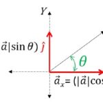
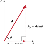
3. Draw the components of the vector. The components are the sides of the parallelogram. The tail of the components start at the tail of the vector and stretches along the axes to the nearest corner of the parallelogram. Be sure to place arrowheads on these components to indicate their direction (up, down, left, right).
4. Meaningfully label the components of the vectors with symbols to indicate which component represents which side. A northward force component might be labeled Fnorth. A rightward velocity component might be labeled vx; etc.
5. Measure the length of the sides of the parallelogram and use the scale to determine the magnitude of the components in real units. Label the magnitude on the diagram.
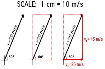
The step-by-step procedure above is illustrated in the diagram below to show how a velocity vector with a magnitude of 50 m/s and a direction of 60 degrees above the horizontal may be resolved into two components. The diagram shows that the vector is first drawn to scale in the indicated direction; a parallelogram is sketched about the vector; the components are labeled on the diagram; and the result of measuring the length of the vector components and converting to m/s using the scale. (NOTE: because different computer monitors have different resolutions, the actual length of the vector on your monitor may not be 5 cm.)