Vectors can be directed due East, due West, due South, and due North. But some vectors are directed northeast (at a 45 degree angle); and some vectors are even directed northeast, yet more north than east. Thus, there is a clear need for some form of a convention for identifying the direction of a vector that is not due East, due West, due South, or due North. There are a variety of conventions for describing the direction of any vector. The two conventions that will be discussed and used in this unit are described below:
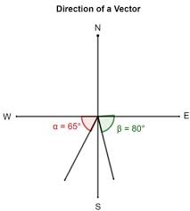
1. The direction of a vector is often expressed as an angle of rotation of the vector about its “tail” from east, west, north, or south. For example, a vector can be said to have a direction of 40 degrees North of West (meaning a vector pointing West has been rotated 40 degrees towards the northerly direction) of 65 degrees East of South (meaning a vector pointing South has been rotated 65 degrees towards the easterly direction).
2. The direction of a vector is often expressed as a counterclockwise angle of rotation of the vector about its “tail” from due East. Using this convention, a vector with a direction of 30 degrees is a vector that has been rotated 30 degrees in a counterclockwise direction relative to due east. A vector with a direction of 160 degrees is a vector that has been rotated 160 degrees in a counterclockwise direction relative to due east. A vector with a direction of 270 degrees is a vector that has been rotated 270 degrees in a counterclockwise direction relative to due east. This is one of the most common conventions for the direction of a vector and will be utilized throughout this unit.
Two illustrations of the second convention (discussed above) for identifying the direction of a vector are shown below.

Observe in the first example that the vector is said to have a direction of 40 degrees. You can think of this direction as follows: suppose a vector pointing East had its tail pinned down and then the vector was rotated an angle of 40 degrees in the counterclockwise direction. Observe in the second example that the vector is said to have a direction of 240 degrees. This means that the tail of the vector was pinned down and the vector was rotated an angle of 240 degrees in the counterclockwise direction beginning from due east. A rotation of 240 degrees is equivalent to rotating the vector through two quadrants (180 degrees) and then an additional 60 degrees into thethird quadrant.
 Representing the Magnitude of a Vector
The magnitude of a vector in a scaled vector diagram is depicted by the length of the arrow. The arrow is drawn a precise length in accordance with a chosen scale. For example, the diagram at the right shows a vector with a magnitude of 20 miles. Since the scale used for constructing the diagram is 1 cm = 5 miles, the vector arrow is drawn with a length of 4 cm. That is, 4 cm x (5 miles/1 cm) = 20 miles.
Using the same scale (1 cm = 5 miles), a displacement vector that is 15 miles will be represented by a vector arrow that is 3 cm in length. Similarly, a 25-mile displacement vector is represented by a 5-cm long vector arrow. And finally, an 18-mile displacement vector is represented by a 3.6-cm long arrow. See the examples shown below.

In conclusion, vectors can be represented by use of a scaled vector diagram. On such a diagram, a vector arrow is drawn to represent the vector. The arrow has an obvious tail and arrowhead. The magnitude of a vector is represented by the length of the arrow. A scale is indicated (such as, 1 cm = 5 miles) and the arrow is drawn the proper length according to the chosen scale. The arrow points in the precise direction. Directions are described by the use of some convention. The most common convention is that the direction of a vector is the counterclockwise angle of rotation which that vector makes with respect to due East.


