A servo motor controller is a circuit that is used to control the position of a servo motor. It is also called as a servo motor driver. A servo motor controller consists of a controller, the servo motor and the power supply unit.Servo motor driver may be used to control a single servo or even a group of servo motors. In many projects where servo motor controlling is the mainstay of the task to be accomplished, the controller must drive more than one servo. An example of this is an RC airplane, which uses many servos.
Essential Components
1. A micro-controller
2. A power supply unit
Miscellaneous Components
1. A potentiometer
2. Connectors, wires etc.
A servo motor is driven by applying the voltage signal to it regular intervals. The servo is sensitive to timing variations. A pulse of specific width has to be applied at specific intervals of time. Typically, the duration of pulse varies from 0ms to 2.2ms and the repetition rate is 50Hz to 60Hz. For precise position control, the controller that is chosen must have timers that have the required resolution. Also, if more than one motor has to be controlled simultaneously, the processor clock must be fast enough. For a single motor control, an 8051 can be used like a AT89s51 or a P89v51RD2. But for more than one motor, we must use a PIC, like a PIC18F or a ATMEGA, so that it’s internal PWM can be utilized. However, the selection of micro-controller depends totally on the designer and the project requirements.
The design of the power supply unit servo motor controller depends on the number of servo motors that are interfaced to the board. Servo motors operate from 4.8V to a 6V supply voltage. The typical value is 5v. Applying voltages greater than the supply voltage is not advisable as it may render the motor permanently useless. The current draw of the motor is variable and depends on the torque that it generates. Also it will draw less current when in idle mode and more current when it is running. A servo motors maximum current draw is given as its stall current. This is the maximum current it will draw when running with the maximum torque before it stops due to overload. This current value can be as high as 1 A for some motors.
For a single motor control a voltage regulator like a LM317 can be used along with a suitable heat sink. But when multiple motors need to be interfaced, a high quality supply with higher current rating must be used. A SMPS (Switched mode power supply) can be a good option.
Block Diagram below showing interconnections in a Servo Motor Driver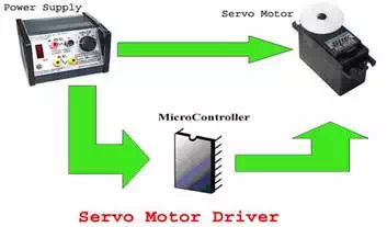
Controlling Servo Motor
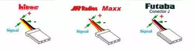
The servo motor has three terminals.
1. Position signal(PWM Pulses)
2. Vcc (From Power Supply)
3. Ground
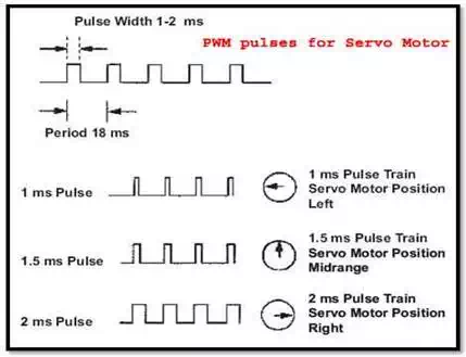
The servo motor angular position is controlled by applying PWM pulses of specific width. The duration of pulse varies from about 0.5 ms for 0 degree rotation to 2.2 ms for 180 degree rotation. The pulses need to be given at frequencies of about 50Hz to 60Hz.
In order to generate the PWM (Pulse Width Modulation) waveform, as shown in figure below, one can use either the internal PWM module of the micro-controller or the timers can be used. Using the PWM block is more flexible as most micro-controller families design the blocks to suit the needs of application like Servo motor. For different widths of PWM pulses, we need to program the internal registers accordingly.
Now, we also need to tell the microcontroller how much it has to rotate. For this purpose, we can use a simple potentiometer and use an ADC to get the rotation angle or for more complex applications an accelerometer can be used.
Program Algorithm
Let us design the Program to control a single servo and the position input is given via the potentiometer connected to a pin of controller.
1. nitialize the port pins for input/output.
2. Read the ADC for desired servo position.
3. Program the PWM registers for the desired value.
As soon as you trigger the PWM module, the selected PWM channel pin goes high (logic 1) and after the required width is reached, it will again go low (logic 0). So after triggering the PWM, you must start a timer with a delay of about 19 ms and wait until the timer overflows
4. Go to step 2
There are various modes of PWM available which you can use depending on the microcontroller you choose. Some degree of optimization should be done in the code to control the servo.
If you plan to use more than one servo than you will require as many PWM channels. Each servo can be given the PWM signal sequentially. But you must take care that the pulse repetition rate for each servo is maintained. Otherwise the servo will run out of synchronization.
Note
If you plan on making your own board for the servo motor controller, give proper thickness for tracks carrying the current to the servo. Proper ERC and DRC rule check must be followed. The PWM signals for a continuous rotation servo are not same as that of a 180 degree servo. The servo datasheet should be consulted for such motors.
A servo motor is critical to voltage fluctuations and too high voltage may damage the internal feedback control circuit. So the power supply must be thoroughly designed to the servo specifications and checked before deployment. Heat sink must be used if necessary.