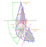
Problem – 1 Section of Solids – A cone with base circle diameter 60 mm and axis length 75 mm is kept on its base on the ground. It is cut by a sectional plane perpendicular to H.P. and inclined at 600 to V.P. at a distance of 8 mm away from the top view of axis. Draw sectional elevation and true shape of the section.
Procedure:
Step-1 Draw a horizontal x-y line of some suitable length.
Step-2 Draw a circle of diameter 60 mm below the x-y line at some suitable distance from it. And divide this circle into 12 equal divisions as shown into the figure. Give notations on it.
Step-3 From the center of the circle, draw a vertical center line of length 75 mm from the x-y line as shown into the figure. And from these notations of the circle draw vertical projectors up to x-y line, and then converge all these projectors at the end of the center line i.e. apex of the cone (point o’) as shown into the figure. It is a triangular shape. And Give the notations on it.
Step-4 Draw a circle of radius 8 mm from the center of the circle in the top view, and draw a cutting plane line i.e., Long chain line thick at ends and thin elsewhere, such that this cutting plane line should be inclined at an angle 60° with the x-y line and tangent to the circle of the radius 8 mm.
Step-5 Give the cutting points name at the intersection of the previously drawn cutting plane line with the divisional lines of the circle & periphery of the circle, i.e., 1,2,3, etc. as shown into the figure.
Step-6 From these cutting points draw vertical projectors such that these projectors will intersect at the respective generators in the front view. And give the name of these cutting points in the front view as shown into the figure. From these cutting points draw a medium dark smooth free hand curve and draw hatching lines in it as shown into the figure. It is the Sectional Front View.
Step-7 Now draw a line x’-y’, parallel with the cutting plane line in the top view, which should be outside of the boundary of the top view as shown into the figure. From the cutting points in the top view draw projectors which should be perpendicular to the cutting plane line and should be of some suitable length as shown into the figure.
Step-8 Now measure the distance of the cutting points from the x-y line, into the Sectional Front View and transfer the same at the respective projectors drawn from the cutting points in the top view, on the previously drawn x’-y’ line, which is parallel to the cutting plane line in the top view.
Step-9 From these transferred points draw a medium dark smooth free hand curve and draw hatching lines in it. It is the True Shape of the section.
Step-10 Give the dimensions by any one method of dimensions and give the notations as shown into the figure.