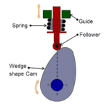
Cam follower systems are designed to achieve a desired oscillatory motion. Appropriate displacement patterns are to be selected for this purpose, before designing the cam surface. The cam is assumed to rotate at a constant speed and the follower raises, dwells, returns to its original position and dwells again through specified angles of rotation of the cam, during each revolution of the cam.
Some of the standard follower motions are as follows: They are, follower motion with,
(a) Uniform velocity
(b) Modified uniform velocity
(c) Uniform acceleration and deceleration
(d) Simple harmonic motion
Displacement diagrams: In a cam follower system, the motion of the follower is veryimportant. Its displacement can be plotted against the angular displacement θ of the cam and it is called as the displacement diagram. The displacement of the follower is plotted along the y-axis and angular displacement θ of the cam is plotted along x-axis. From the displacement diagram, velocity and acceleration of the follower can also be plotted for different angular displacements θ of the cam. The displacement, velocity and acceleration diagrams are plotted for one cycle of operation i.e., one rotation of the cam. Displacement diagrams are basic requirements for the construction of cam profiles. Construction of displacement diagrams and calculation of velocities and accelerations of followers with different types of motions are discussed in the following sections.
Displacement, Velocity and Acceleration Diagrams when the Follower Moves with Uniform Velocity
Fig.3.8 shows the displacement, velocity and acceleration patterns of a follower having uniform velocity type of motion. Since the follower moves with constant velocity, during rise and fall, the displacement varies linearly with θ. Also, since the velocity changes from zero to a finite value, within no time, theoretically, the acceleration becomes infinite at the beginning and end of rise and fall.

Fig.3.8
Displacement, Velocity and Acceleration Diagrams when the Follower Moves with Simple Harmonic Motion
In fig.3.9, the motion executed by point Pl, which is the projection of point P on the vertical diameter is called simple harmonic motion. Here, P moves with uniform angular velocity ωp, along a circle of radius r (r = s/2).


