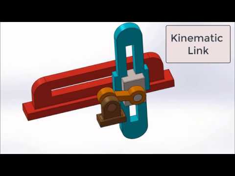
A machine part or a component of a mechanism is called a kinematic link or simply a link. A link is assumed to be completely rigid, or under the action of forces it does not suffer any deformation, signifying that the distance between any two points on it remains constant. Although all real machine parts are flexible to some degree, it is common practice to assume that deflections are negligible and parts are rigid when analyzing a machine’s kinematic performance.
Types of link
(a) Based on number of elements of link:

Binary link: Link which is connected to other links at two points.
Ternary link: Link which is connected to other links at three points.
Quaternary link: Link which is connected to other links at four points.
(a) Based on type of structural behavior:
Sometimes, a machine member may possess one-way rigidity and is capable of transmitting the force in one direction with negligible deformation. Examples are (a) chains, belts and ropes which are resistant to tensile forces, and (b) fluids which are resistant to compressive forces and are used as links in hydraulic presses, brakes and jacks. In order to transmit motion, the driver and the follower may be connected by the following three types of links:
1. Rigid link. A rigid link is one which does not undergo any deformation whiletransmitting motion. Strictly speaking, rigid links do not exist. However, as the deformation of a connecting rod, crank etc. of a reciprocating steam engine is not appreciable, they can be considered as rigid links.
2. Flexible link. A flexible link is one which is partly deformed in a manner not to affectthe transmission of motion. For example, belts, ropes, chains and wires are flexible links and transmit tensile forces only.
3. Fluid link. A fluid link is one which is formed by having a fluid in a receptacle and themotion is transmitted through the fluid by pressure or compression only, as in the case of hydraulic presses, jacks and brakes.


