The most important feature in eddy current testing is the way in which the eddy currents are induced and detected in the material under test. This depends on the design of the probe. As discussed in the previous pages, probes can contain one or more coils, a core and shielding. All have an important effect on the probe, but the coil requires the most design consideration.
A coil consists of a length of wire wound in a helical manner around the length of a former. The main purpose of the former is to provide a sufficient amount of rigidity in the coil to prevent distortion. Formers used for coils with diameters greater than a few millimeters (i.e. encircling and pancake coils), generally take the form of tubes or rings made from dielectric materials. Small-diameter coils are usually wound directly onto a solid former.
The region inside the former is called the core, which can consist of either a solid material or just air. When the core is air or a nonconductive material, the probe is often referred to as an air-core probe. Some coils are wound around a ferrite core which concentrates the the coil’s magnetic field into a smaller area. These coils are referred to as “loaded” coils.
The wire used in an eddy current probe is typically made from copper or other nonferrous metal to avoid magnetic hysteresis effects. The winding usually has more than one layer so as to increase the value of inductance for a given length of coil. The higher the inductance (L) of a coil, at a given frequency, the greater the sensitivity of eddy current testing.
It is essential that the current through the coil is as low as possible. Too high a current may produce:
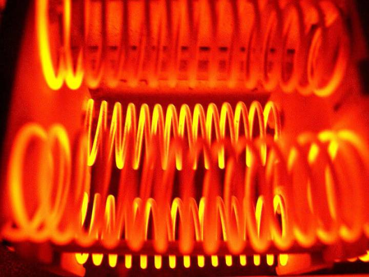
● a rise in temperature, hence an expansion of the coil, which increases the value of L.
● magnetic hysteresis, which is small but detectable when a ferrite core is used.
The value of L is given by:
L = Kn2 p [ (ro2 – rc2) – µrrc2] µo / l
● ro is the mean radius of the coil.
● rc is the radius of the core.
● l is the length of the coil.
● n is the number of turns.
● µr is the relative magnetic permeability of the core.
● µo is the permeability of free space (i.e. 4 pi x 10-7 H/m).
● K is a dimensionless constant characteristic of the length and the external and internal radii.