Phase lag is a parameter of the eddy current signal that makes it possible to obtain information about the depth of a defect within a material. Phase lag is the shift in time between the eddy current response from a disruption on the surface and a disruption at some distance below the surface. The generation of eddy currents can be thought of as a time dependent process, meaning that the eddy currents below the surface take a little longer to form than those at the surface. Disruptions in the eddy currents away from the surface will produce more phase lag than disruptions near the surface. Both the signal voltage and current will have this phase shift or lag with depth, which is different from the phase angle discussed earlier. (With the phase angle, the current shifted with respect to the voltage.)
Phase lag is an important parameter in eddy current testing because it makes it possible to estimate the depth of a defect, and with proper reference specimens, determine the rough size of a defect. The signal produced by a flaw depends on both the amplitude and phase of the eddy currents being disrupted. A small surface defect and large internal defect can have a similar effect on the magnitude of impedance in a test coil. However, because of the increasing phase lag with depth, there will be a characteristic difference in the test coil impedance vector.
Phase lag can be calculated with the following equation. The phase lag angle calculated with this equation is useful for estimating the subsurface depth of a discontinuity that is concentrated at a specific depth. Discontinuities, such as a crack that spans many depths, must be divided into sections along its length and a weighted average determined for phase and amplitude at each position below the surface.
| InRadians | 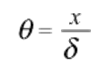 |
| InDegrees | 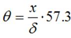 |
| Where: | |
| q=Phase Lag (Rad or Degrees)x=Distance Below Surface (in or mm)d=Standard Depth of Penetration (in or mm) |
At one standard depth of penetration, the phase lag is one radian or 57o. This means that the eddy currents flowing at one standard depth of penetration (d) below the surface, lag the surface currents by 57o. At two standard depths of penetration (2d), they lag the surface currents by 114o. Therefore, by measuring the phase lag of a signal the depth of a defect can be estimated.
On the impedance plane, the liftoff signal serves as the reference phase direction. The angle between the liftoff and defect signals is about twice the phase lag calculated with the above equation. As mentioned above, discontinuities that have a significant dimension normal to the surface, will produce an angle that is based on the weighted average of the disruption to the eddy currents at the various depths along its length.
In the applet below, the relationship between the depth and dimensions of a discontinuity and the rotation produced on the impedance plane is explored. The red lines represent the relative strength of the magnetic field from the coil and the dashed lines indicate the phase lag of the eddy currents induced at a particular depth.