Simple machine, any of several devices with few or no moving parts that are used to modify motion and force in order to perform work. The simple machines are the inclined plane, lever, wedge, wheel and axle, pulley, and screw.
The Inclined Plane
An inclined plane consists of a sloping surface; it is used for raising heavy bodies. The plane offers a mechanical advantagein that the force required to move an object up the incline is less than the weight being raised (discounting friction). The steeper the slope, or incline, the more nearly the required force approaches the actual weight. Expressed mathematically, the force F required to move a block D up an inclined plane without friction is equal to its weight W times the sine of the angle the inclined plane makes with the horizontal (θ). The equation is F = W sin θ.
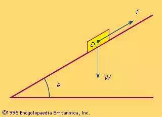
inclined planeIn this representation of an inclined plane, D represents a block to be moved up the plane, F represents the force required to move the block, and W represents the weight of the block. Expressed mathematically, and assuming the plane to be without friction, F =W sin θ.
The principle of the inclined plane is used widely—for example, in ramps and switchback roads, where a small force acting for a distance along a slope can do a large amount of work.
The Lever
A lever is a bar or board that rests on a support called a fulcrum. A downward force exerted on one end of the lever can be transferred and increased in an upward direction at the other end, allowing a small force to lift a heavy weight.
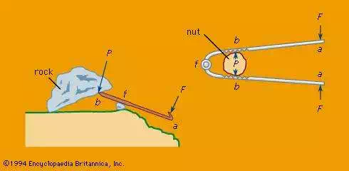
leversTwo examples of levers(Left) A crowbar, supported and turning freely on a fulcrum f, multiplies a downward force F applied at point a such that it can overcome the load Pexerted by the mass of the rock at point b. If, for example, the length af is five times bf, the force F will be multiplied five times. (Right) A nutcracker is essentially two levers connected by a pin joint at a fulcrum f. If af is three times bf, the force F exerted by hand at point a will be multiplied three times at b, easily overcoming the compressive strength P of the nutshell.
All early people used the lever in some form, for example, for moving heavy stones or as digging sticks for land cultivation. The principle of the lever was used in the swape, or shadoof, a long lever pivoted near one end with a platform or water container hanging from the short arm and counterweights attached to the long arm. A man could lift several times his own weight by pulling down on the long arm. This device is said to have been used in Egypt and India for raising water and lifting soldiers over battlements as early as 1500 BCE.
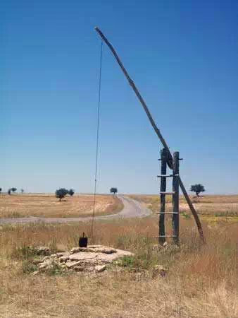
shadoofShadoof, central Anatolia, Turkey.
The Wedge
A wedge is an object that tapers to a thin edge. Pushing the wedge in one direction creates a force in a sideways direction. It is usually made of metal or wood and is used for splitting, lifting, or tightening, as in securing a hammer head onto its handle.
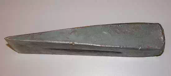
wedgeWedge used for splitting wood.
The wedge was used in prehistoric times to split logs and rocks; an ax is also a wedge, as are the teeth on a saw. In terms of its mechanical function, the screw may be thought of as a wedge wrapped around a cylinder.
The Wheel And Axle
A wheel and axle is made up of a circular frame (the wheel) that revolves on a shaft or rod (the axle). In its earliest form it was probably used for raising weights or water buckets from wells.
Its principle of operation is best explained by way of a device with a large gear and a small gear attached to the same shaft. The tendency of a force, F, applied at the radius R on the large gear to turn the shaft is sufficient to overcome the larger force W at the radius r on the small gear. The force amplification, or mechanical advantage, is equal to the ratio of the two forces (W:F) and also equal to the ratio of the radii of the two gears (R:r).
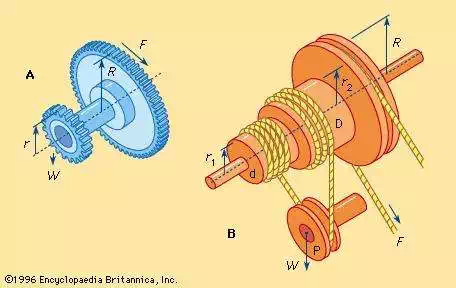
wheel and axle arrangementsTwo wheel and axle arrangements(A) With a large gear and a small gear attached to the same shaft, or axle, a force F applied at the radius R on the large gear is sufficient to overcome the larger force W at the radius r on the small gear, turning the axle. (B) In a drum and rope arrangement capable of raising weights, a large drum of radius R can be used to turn a small drum. An increase in mechanical advantage can be obtained by using the large drum to turn a small drum with two radii as well as a pulley block. When a force F is applied to the rope wrapped around the large drum, the rope wrapped around the small two-radius drum winds off of d (radius r1) and onto D (radius r2). The force W on the radius of the pulley block P is easily overcome, and the attached weight is lifted.
If the large and small gears are replaced with large- and small-diameter drums that are wrapped with ropes, the wheel and axle becomes capable of raising weights. The weight being lifted is attached to the rope on the small drum, and the operator pulls the rope on the large drum. In this arrangement the mechanical advantage is the radius of the large drum divided by the radius of the small drum. An increase in the mechanical advantage can be obtained by using a small drum with two radii, r1 and r2, and a pulley block. When a force is applied to the large drum, the rope on the small drum winds onto D and off of d.
A measure of the force amplification available with the pulley-and-rope system is the velocity ratio, or the ratio of the velocityat which the force is applied to the rope (VF) to the velocity at which the weight is raised (VW). This ratio is equal to twice the radius of the large drum divided by the difference in the radii of the smaller drums D and d. Expressed mathematically, the equation is VF/VW = 2R/(r2 – r1). The actual mechanical advantage W/F is less than this velocity ratio, depending on friction. A very large mechanical advantage may be obtained with this arrangement by making the two smaller drums D and d of nearly equal radius.
The Pulley
A pulley is a wheel that carries a flexible rope, cord, cable, chain, or belt on its rim. Pulleys are used singly or in combination to transmit energy and motion. Pulleys with grooved rims are called sheaves. In belt drive, pulleys are affixed to shafts at their axes, and power is transmitted between the shafts by means of endless belts running over the pulleys.
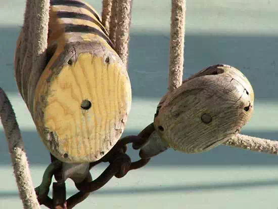
pulleyPulley.GK Bloemsma
One or more independently rotating pulleys can be used to gain mechanical advantage, especially for lifting weights. The shafts about which the pulleys turn may affix them to frames or blocks, and a combination of pulleys, blocks, and rope or other flexible material is referred to as a block and tackle. The Greek mathematician Archimedes (3rd century BCE) is reported to have used compound pulleys to pull a ship onto dry land.
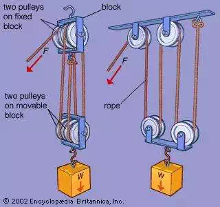
Block and tackle
The Screw
A screw is a usually circular cylindrical member with a continuous helical rib, used either as a fastener or as a force and motion modifier.
Although the Pythagorean philosopher Archytas of Tarentum(5th century BCE) is the alleged inventor of the screw, the exact period of its first appearance as a useful mechanical device is obscure. The invention of the water screw is usually ascribed to Archimedes, but evidence exists of a similar device used for irrigation in Egypt at an earlier date. The screw press, probably invented in Greece in the 1st or 2nd century BCE, has been used since the days of the Roman Empire for pressing clothes. In the 1st century CE, wooden screws were used in wine and olive-oil presses, and cutters (taps) for cutting internal threads were in use.
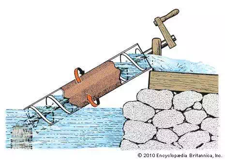
Archimedes screwArchimedes screw.
Cap and machine screws are used to clamp machine parts together, either when one of the parts has a threaded hole or in conjunction with a nut. These screws stretch when tightened, and the tensile load created clamps the parts together. The setscrew fits into a threaded hole in one member; when tightened, the cup-shaped point is pressed into a mating member (usually a shaft) and prevents relative motion. Self-tapping screws form or cut mating threads by displacing material adjacent to a pilot hole so that it flows around the screw.
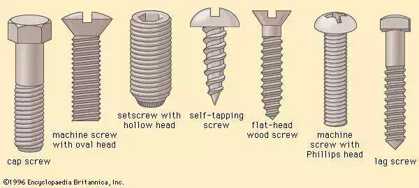
Screws and screw heads (A) Cap screw, (B) machine screw with oval head, (C) setscrew with hollow head, (D) self-tapping screw, (E) flat-head wood screw, (F) machine screw with Phillips head, (G) lag screw
Wood screws are made in a wide variety of diameters and lengths; when using the larger sizes, pilot holes are drilled to avoid splitting the wood. Lag screws are large wood screws used to fasten heavy objects to wood. Heads are either square or hexagonal.
Screws that modify force and motion are known as power screws. A screw jack converts torque (turning moment) to thrust. The thrust (usually to lift a heavy object) is created by turning the screw in a stationary nut. By using a long bar to turn the screw, a small force at the end of the bar can create a large thrust force. Workpiece tables on machine tools are moved linearly on guiding ways by screws that rotate in bearings at the ends of the tables and mate with nuts fixed to the machine frame. A similar torque-to-thrust conversion can be obtained by either rotating an axially fixed screw to drive a rotationally fixed nut along the screw or by rotating an axially fixed nut to drive a rotationally fixed screw through the nut.