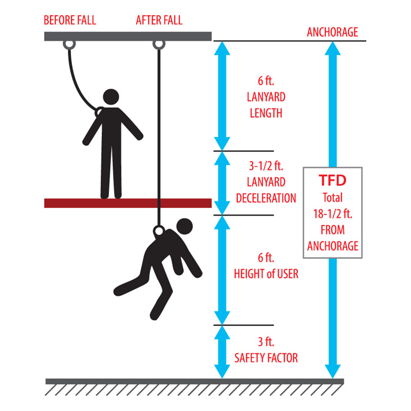
You have just received your new full body harness, 6-ft. shock-absorbing lanyard and anchorage connector. A structural engineer qualified all of your anchor points to ensure that they meet strength requirements per OSHA regulations. Is your personal fall arrest system complete? Perhaps not.
If you have not determined available clearance below the working surface and calculated your total
fall distance (TFD) properly, it may still be possible to be seriously or fatally injured in the event of a fall.
Courtesy of MSA, provided below is the information you need to accurately calculate total fall distance.
Knowing how to calculate total fall distance is just as critical as selecting the proper harness, lanyard, anchorage connector, and anchorage point for your specific application. Total fall distance is defined as the sum of freefall distance (FFD), deceleration distance (DD), harness effects (HEFF), and vertical elongation (VEL). It is also wise to include a safety factor (SF) of at least 2-ft. in the formula. Total fall distance can be calculated using the following formula: TFD = FFD + DD + HEFF + VEL + SF
Before we calculate total fall distance, we must define variables used in the formula shown above:
Freefall Distance (FFD):
Vertical distance that a worker travels between onset of a fall until just prior to the point where the fall arrest system arrests the fall. To minimize FFD, always attempt to keep your anchor point as far above the harness back D-ring as possible. If the only anchor point is below the back D-ring, be sure to select a lanyard or SRL that is approved for the greater resulting FFD. Deceleration Distance (DD): Vertical distance that a worker travels between fall arrest system activation and final fall arrest. The DD that each shock-absorbing fall arrest device will permit is typically stated on the product label.
Harness Effects (HEFF):
Stretch of a harness during fall arrest, typically 1-ft. or fewer for a properly fitted harness. However, some harnesses use elastic-type webbing that can increase harness effects to 2-ft. or more. Vertical Elongation (VEL): Stretch of the personal fall arrest system lifeline. Vertical elongation is measured on the area of the lifeline that is under tension during deceleration and final fall arrest. This variable will change drastically, depending upon the type of fall arrest system used. For example, most shock-absorbing lanyards are designed to have maximum deceleration distance of 4-ft., including lanyard vertical elongation. However, if you use a rope grab system or horizontal lifeline, vertical elongation must be calculated based upon stretch of the vertical or horizontal lifelines in those systems. You must check the specific manufacturer’s product for exact stretch percentages.
Safety Factor (SF):
Additional safety factor to ensure that you have required clearance below your working surface. This variable should be at least 2-ft., but can reflect any number with which you feel comfortable.
Safety Factor (SF):
Additional safety factor to ensure that you have required clearance below your working surface. This variable should be at least 2-ft., but can reflect any number with which you feel comfortable. For illustration purposes, we’ll discuss use of the following equipment:
§ Full body harness (non-elastic)
§ 6-ft. shock-absorbing lanyard
§ Fixed, rigid anchorage connector (such as a D-plate bolted to a structural I-beam)

In the figure to the left, we see a worker wearing a 6-ft. shock-absorbing lanyard standing on an elevated platform. If his anchor point was even with his harness back D-ring, his FFD will equal his lanyard length. In this example, let’s assume that his at tachment point is 2-ft. above the back D-ring. For every 1-ft. that the lanyard attachment point is above the harness back D-ring, 1-ft. is deducted from freefall distance. For every 1-ft. that the lanyard attachment point is below the harness back D-ring, 1-ft. is added to freefall distance (Table 1 below). Using this scenario, if the worker falls, freefall distance (FFD) will equal 4-ft., as the lanyard attachment point is 2-ft. above the harness back Dring. As a result, our formula is as follows: TFD = 4-ft. + DD + HEFF + VEL + SF

The next variable to consider is deceleration distance (DD). As all manufactured products are slightly different, be sure to read the label of the product intended for use to determine that product’s maximum deceleration distance. When calculating total fall distance, maximum deceleration distance that a product will permit should always be used. In our example, maximum deceleration distance would be 4-ft. TFD = 4-ft. + 4-ft. +HEFF + VEL + SF
The harness effects variable is relatively constant at less than 1-ft. This factor will vary slightly due to harness adjustment, so we generally use 1-ft. to account for these slight differences. However, elastictype harnesses can have more than 1-ft. of stretch, possibly 2-ft. or more; that additional distance must be accounted for in your calculation. In our example, we use a non-elastic harness to minimize total fall distance. TFD = 4ft. + 4ft. + 1ft. + VEL + SF Most manufacturers design shock-absorbing lanyards so that lanyard vertical elongation is included in maximum deceleration distance.
However, if we were to use a rope grab or horizontal lifeline, or if you were to attach to a non-rigid anchorage connector, VEL should be calculated based upon specifications of fall arrest system components. As we are using a 6-ft. shock-absorbing lanyard in our example and VEL is already considered in lanyard design, we will enter 0 for the VEL variable. TFD = 4ft. + 4ft. + 1ft. + 0ft. + SF The final formula variable is the safety factor. It’s ideal to include at least a 2-ft. safety factor; however, the safety factor could reflect any number that makes you comfortable with your calculation. Now we can solve our total fall distance formula: TFD = 4ft. + 4ft. + 1ft. + 0ft. +2ft. TFD =11ft
Now we know that should the worker in Figure 1 experience a fall, his total fall distance will be 11-ft. But what is the significance of this number? The number dictates that clearance between the working

surface and the next closest object in the fall path must be at least 9.5-ft. It is essential to remember that total fall distance is not always measured from the working surface to the ground, as the ground may not be the closest object beneath the working platform. If any obstruction lies in the worker’s fall path (Figure 2 to the right), available clearance is measured from the working platform to the top of that obstruction. Sometimes these distances can be very short; in such cases, fall protection equipment other than a 6-ft. shock-absorbing lanyard is necessary.
Total fall distance calculations can be more complex than those demonstrated here. Numbers and variables will change depending upon the type of personal fall arrest system used. For example, when calculating total fall distances for horizontal lifeline systems, additional variables should be considered, such as cable deflection and number of workers on the system. Calculating total fall distance is just as crucial as selecting the right product for the job. Neglecting to calculate total fall distance is just as potentially hazardous as neglecting to don your harness before performing any work at heights.


