Working principle:
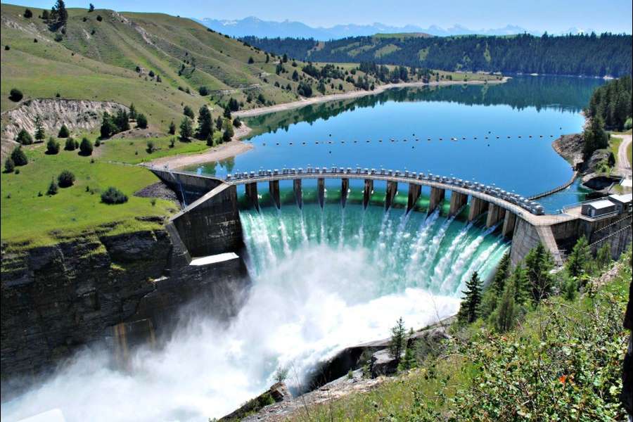
Dam is built through the river and water is stored, from that hydroelectric power plant operates to develop the potential energy. From the stored water the potential energy is converted into the kinetic energy. With the help of the penstock pipe the water must flows through it as it generates the energy. In the water turbine the developed kinetic energy must be converted into the mechanical energy. Here, to the electric generator the turbine is coupled. In the turbine at the shaft the mechanical energy is converted into the electrical energy with the help of generator. Due to gravity it provides the force which allows the water to flow, in this water the stored energy is known as gravitational potential energy.

Layouts of hydroelectric power plant:
- Dam
- Water reservoir
- Gate
- Spillway
- Surge tank
- Pressure tunnel
- Penstock
- Water turbine
- Draft tube
- Tail race level
- Power house
Dam:
The main purpose of the dam is to store the water and to control the outgoing run of water. All the incoming water is stored in the dam. The water head is increased with the help of the dam, which is essential when an enough head is available.
Water reservoir:
During rainy season in a reservoir water is collected from the watershed and stored behind the dam. At the time of rainy season, water from rivers is stockpiled behind a dam. Nonstop accessibility of water is an elementary requirement for a hydroelectric power plant. In the reservoir the level of surface water is called head water level. The available water head for power generation hang on the reservoir height
Gate:
The main purpose of the gate is used to control the flow of water from dam.
Spillway:
High amount of water in the reservoir leads to the damage of the reservoir so that a stable state of water is maintained in the dam. During rainy seasons spillways are provided to avoid the water flow and to release the water outside. So the risk factor must be reduced and the water level in the dam also comes down. The excess water present in the storage area is allowed outside by using the spillways.
Surge Tank:
It is a small tank or a reservoir in which the water level falls or rises due to sudden pressure change. Due to sudden increment of the pressure in the penstock pipe we can notice the sudden backflow of the water. On the turbine the load must be decreased. The rapid rise of pressure in the penstock pipe is called as water hammer. The surge tank is situated between the turbine and dam to serve the water at the time of need.
By reducing the gap between the turbine and the dam is in the way of reducing the water hammer effect also. It functions as a source tank to the turbine, while the water in the pipe is enhanced during amplified load conditions, as storage tank when the water is slow down during compact load conditions.
Pressure tunnel
By using the pressure tunnel the water passes from the reservoir to the surge tank.
Penstock
The main aim of the penstock is to bring the water from the dam to the hydraulic turbine. The pipes are made up of reinforced concrete or steel. In the dam at low level the turbines are to be installed. At the inlet, gate is delivers to the penstocks in order to close the water supply. To control the water flow rate it delivers gate valve at the inlet to totally close by the water supply. It has a regulator valve to switch the water flow rate into the turbine
Water turbine
The water turbine is also known as hydraulic turbine. The turbine converts the water energy into the mechanical energy. On the turbine shaft the available mechanical energy, this is joined to the shaft for the electrical generator which produces the electrical energy. The water present in the turbine blade is discharged through the draft tube. The prime motivators which are in mutual use are Kaplan turbine, Pelton wheel and Francis turbine
Draft tube
Draft tube is linked to the exit of the turbine. It exchanges the kinetic energy offered in the water into pressure energy in the differing portion. It retains a pressure of impartial in the atmospheric at exist of the draft tube to run the water into a tail race. From the tail race water is released for irrigation purposes.
Tail race level
Tail race is a water path to lead the water exiting from the turbine to the canal or river. In the tail race the water detained is called Tailrace water level
Power house
- The power houses provide accommodations the generator, transformer and water turbine and along with control room.
- If the water flows through the turbine, there water turns the turbine shaft, and it is joined to the electric generator.
- A rotating electromagnet is attached to generator it called a rotor and a motionless part called as a stator.
- A magnetic field that produces with the help of rotor and an electric charge is produced in the stator.
- The charge is transferred as electricity. The step up transformer raises the voltage of the current coming from the stator. Through the power lines the electricity is distributed


