Profile is one the five types of GD&T control. This geometric dimension and Tolerancing tutorial will be concentrating over the different profile types of GD&T controls with examples.
ASME Y14.5 talks about five categories of geometric dimensioning and Tolerance (GD&T) controls. Profile is one among them. The Profile itself has two subtypes of GD&T control: Profile of a line and profile of curve.
Profile of a Line
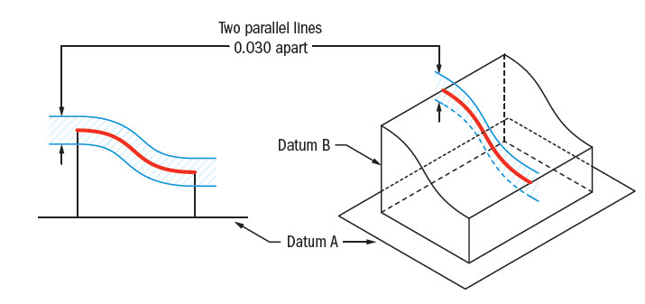
This GD&T symbol controls the profile of a line (straight or curved) in a 2D tolerance space.

The above example signifies that at both the cross sections (X-X and Y-Y), the arrow marked curved line should lie between a tolerance zone of 0.2. For locating the maiden line of the boundary lines of the 0.2 tolerance zone, we have used two datums. However, using of datum is not mandatory for the profile of a line GD&T control.
Profile of a Surface
The profile of a surface is the 3D form of the profile of a line GD&T control. By applying profile of a surface control, we ensure that the indicated curved (or flat) surface should lie in between a set of parallel surfaces with specified distance.

In the above example, the profile of a surface tolerance is applied as 0.2, means the whole curved surface should lie between a set of equilateral parallel surfaces 0.2 apart.
General Rules for Using the Profile Controls
○ The profile types of GD&T tolerance are used for controlling a curved (or flat sometimes) surfaces and the edges of the surfaces.
○ Profile tolerances may or may not use datum.
○ If nothing is specified, profile tolerance zone is unilateral against the ideal surface or curve.
○ For refinement of profile tolerance, two single segment feature control frame can be used.
Conclusion
The profile types of geometric dimensioning and Tolerancing controls are used to control the form of geometry. There are two sub-types under the profile types of GD&T. These GD&T symbols are used 2D (profile of a line) as well as 3D (profile of a surface) geometric features.


