
Traditional Process Planning:
There are variations in the level of detail found in route sheets among different companies & industries. In the one extreme, process planning is accomplished by releasing the part print to the production shop with the instructions “make to drawing.” Most firms provide a more detailed list of steps describing each operation and identifying each work centre. In any case, it is traditionally the task of the manufacturing engineers or industrial engineers in an organization to write these process plans for new part designs to be produced by the shop. The process planning procedure is very much dependent on the experience and judgement of the planner. It is the manufacturing engineer’s responsibility to determine an optimal routing for each new part design. However, the individual engineers each have their own opinions about what constitutes the best routing. Accordingly, there are differences among the operation sequences developed by various planners. We can illustrate rather dramatically these differences by means of an example.
In one case, a total of 42 different routings were developed for various sizes of a relatively simple part called an “expander sleeve.” There were a total of 64 different sizes & styles, each with its own part number. The 42 routings included 20 different machine tools in the shop. The reason for this absence of process standardization was that many different individuals had worked on the parts: 8 or 9 manufacturing engineers, 2 planners and 25 NC part programmers. Upon analysis, it was determined that only two different routings through 4 machines were needed to process the 64-part numbers. It is clear that there were potentially great differences in the perceptions among process planners as to what constitutes the “optimal” method of production.
In addition to this problem of variability among planners, there are often difficulties in the conventional process planning procedure. New machine tools in the factory render old routings less than optimal. Machine breakdowns force shop personnel to use temporary routings, & these become the documented routings even after the machine is repaired. For these reasons and others, a significant proportion of the total number of process plans used in manufacturing are not optimal.
Automated Process Planning:
Because of the problems encountered with manual process planning, attempts have been made in recent years to capture the logic, judgement, and experience required for this important function and incorporate them into computer programs. Based on the characteristics of a given part, the program automatically generates the manufacturing operation sequence. A computer-aided process planning (CAPP) system offers the potential for reducing the routine clerical work of manufacturing engineers. At the same time, it provides the opportunity to generate production routings which are rational, consistent, and perhaps even optimal. Two alternative approaches to computer-aided process planning have been developed. These are:
1. Retrieval-type CAPP systems (also called variant systems)
2. Generative CAPP systems
The two types are described as below:
Retrieval-type Process Planning systems:
Retrieval-type CAPP systems use parts classification & coding & group technology as a foundation. In this approach, the parts produced in the plant are grouped into part families, distinguished according to their manufacturing characteristics. For each part family, a standard process plan is established. The standard process plan is stored in computer files & then retrieved for new work parts which belong to that family. Some form of parts classification & coding system is required to organize the computer files & to permit efficient retrieval of the appropriate process plan for a new work part. For some new parts, editing of the existing process plan may be required. This is done when the manufacturing requirements of the new part are slightly different from the standard. The machine routing may be the same for the new part, but the specific operations required at each machine may be different. The complete process plan must document the operations as well as the sequence of machines through which the part must be routed. Because of the alterations that are made in the retrieved process plan, these CAPP systems are sometimes also called by the name “variant system”.
The figure illustrated further will help to explain the procedure used in a retrieval process planning system. The user would initiate the procedure by entering the part code number at a computer terminal. The CAPP program then searches the part family matrix file to determine if a match exists. If the file contains an identical code number, the standard machine routing & operation sequence are retrieved from the respective computer files for display to the user. The standard process plan is examined by the user to permit any necessary editing of the plan to make it compatible with the new part design. After editing, the process plan formatter prepares the paper document in the proper form.
If an exact match cannot be found between the code numbers in the computer file & the code number for the new part, the user may search the machine routing file & the operation sequence file for similar parts that could be used to develop the plan for the new part. Once the process plan for a new part code number has been entered, it becomes the standard process for future parts of the same classification.
In the figure illustrated in the previous slide, the machine routing file is distinguished from the operation sequence file to emphasize that the machine routing may apply to a range of different part families & code numbers. It would be easier to find a match in the machine routing file than in the operation sequence file. Some CAPP retrieval systems would use only one such file which a combination of operation sequence file & machine routing file would be .
The process plan formatter may use other application programs. These could include programs to compute machining conditions, work standards, & standard costs. Standard cost programs can be used to determine total product costs for pricing purposes.
A number of retrieval-type computer-aided process planning systems have been developed. These include MIPLAN, one of the MICLASS modules, the CAPP system developed by Computer-Aided Manufacturing — International, COMCAPP V by MDSI, & systems by individual companies. We will use MIPLAN as an example to illustrate these industrial systems.
MIPLAN is a computer-aided process planning package available from the Organization for Industrial Research, Inc., of Waltham, Massachusetts. It is basically a retrieval-type CAPP system with some additional features. The MIPLAN system consists of several modules which are used in an interactive, conversational mode.
To operate the system, the user can select any of the four different options to create the process plan for a new part:
1. The first option is a retrieval approach in which the user inputs a part code number & a standard process plan is retrieved from the computer file for possible editing. To generate the part code number, the planner may elect to use the MICLASS interactive parts classification & coding system.
2. In the second option, a process play is retrieved from the computer files by entering an existing part number (rather than a part code number). Again, the existing process plan can be edited by the user if required.
3. A process plan can be created from scratch, using standard text material stored in computer files. This option is basically a specialized word-processing system in which the planner selects from a menu of text related to machines & processes. The process plan is assembled from text passages subject to editing for the particular requirements of the new part.
4. The user can call up an incomplete process plan from the computer file. This may occur when the user is unable to complete the process plan for a new part at one sitting. For example, the planner may interrupted in the middle of the procedure to solve some emergency problem. When the procedure is resumed, the incomplete plan can be retrieved & finished.
After the process plan has been completed using one of the four MIPLAN options, the user can have a paper document printed out by the computer. A typical MIPLAN output is shown in the figure in the next slide. It is also possible for the user to store the completed process plan (or the partially completed plan as with the option 3) in the computer files, or to purge an existing plan from the files. This might be done, for example, when an old machine tool is replaced by a more productive machine, & this necessitates changes in some of the standard process plans.
Computer graphics can be utilized to enhance the MIPLAN output. This possibility is illustrated in the next slide, which shows a tooling setup for the machining operation described. With this kind of pictorial process planning, drawings of work part details, tool paths, & other information can be presented visually to facilitate communication to the manufacturing shops.
Generative Process Planning Systems:
Generative Process Planning involves the use of computer to create an individual process plan from scratch, automatically & without human assistance. The computer would employ a set of algorithms to progress through the various technical & logical decisions toward a final plan for manufacturing. Inputs to the system would include a comprehensive description of the work part. This may involve the use of some form of part code number to summarise the work part data, but it does not involve the retrieval of existing standard plans. Instead, the generative CAPP system synthesizes the design of the optimum process sequence, based on an analysis of part geometry, material & other factors which would influence manufacturing decisions.
In the ideal generative process planning package, any part design could be presented to the system for creation of the optimal plan. In practice, current generative-type systems are far from universal in their applicability. They tend fall short of a truly generative capability, and they are developed for a somewhat limited range of manufacturing processes.
We will illustrate the generative process planning by means of a system called GENPLAN developed at Lockheed-Georgia Company
GENPLAN is close to a generative process planning system, but it requires a human planner to assist with some of the manufacturing decisions. Also there are several versions GENPLAN (one for parts fabrication, and another for assembly), which means that it is not a system of universal applicability.
To operate the system, the planner enters a part classification code using a coding scheme developed at Lockheed. GENPLAN then analyses the characteristics of the part based on the code number (e.g., part geometry, work piece material, & other manufacturing related features) to synthesize an optimum process plan. It does not store standard manufacturing plans. Rather, it stores machine tool capabilities & it employs the logic & technological science of manufacturing. The output is a document specifying the sequence of operations, machine tools, & calculated process times. An example of a computer-generated route sheet produced by GENPLAN is shown in the figure in the next slide. Process plans that previously required several hours to accomplish manually are now done typically by GENPLAN in 15 minutes.
Benefits of CAPP:
Whether it is retrieval system or a generative system, computer-aided process planning offers a number of potential advantages over manually oriented process planning.
1. Process rationalization. Computer-automated preparation of operation routings is more likely to be consistent, logical, & optimal than its manual counterpart. The process plans will be consistent because the same computer software is being used by all planners. We avoid the tendency for drastically different process plans from different planners. The process plans tend to be more logical & optimal because the company has presumably incorporated the experience & judgement of its best manufacturing people into the process planning computer software.
2. Increased productivity of process planners. With computer-aided process planning, there is reduced clerical effort, fewer errors are made, & the planners have immediate access to the process planning data base. These benefits translate into higher productivity of the process planners. One system was reported to increase productivity by 600% in the process planning function.
3. Reduced turnaround time. Working with the CAPP system, the process planner is able to prepare a route sheet for a new part in less time compared to manual preparation. This leads to an overall reduction in manufacturing lead time.
4. Improved legibility. The computer prepared document is neater & easier to read than manually written route sheets. CAPP systems employ standard text, which facilitates interpretation of the process plan in the factory.
5. Incorporation of other application programs. The process planning system can be designed to operate in conjunction with other software packages to automate many of the time-consuming manufacturing support functions.
Aggregate Production Planning & The Master Production Schedule:
Aggregate planning is a high-level corporate planning activity. The aggregate production plan indicates production output levels for the major product lines of the company. The aggregate plan must be coordinated with the plans of the sales & marketing departments. Because the aggregate production plan includes products that are currently in production, it must also consider the present & future inventory levels of those products & their component parts. Because new products currently being developed will also be included in the aggregate plan, the marketing plans & promotions for current products & new products must be reconciled against the total capacity resources available to the company.
The production quantities of the major product lines listed in the aggregate plan must be converted into a very specific schedule of individual products, known as the master production schedule (MPS). It is a list of products to be manufactured, when they should be completed & delivered, & it what quantities. A hypothetical MPS for a narrow product set is presented in the table, showing how it is derived from the corresponding aggregate plan in the 2nd table. The master schedule must be based on an accurate estimate of demand & a realistic assessment of the company’s production capacity.
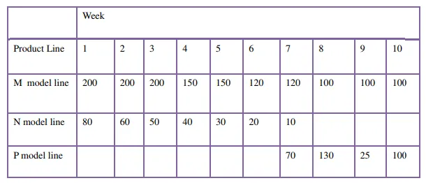
(a) Aggregate Production Plan
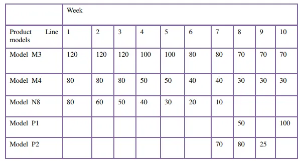
(b) Master Production Schedule
Products included in the MPS divide into 3 categories: (1) firm customer orders, (2) forecasted demand, & (3) spare parts. Proportions in each category vary for different companies, & in some cases one or more categories are omitted. Companies producing assembled products will generally have to handle all three types. In the case of customer orders for specific products, the company is usually obligated to deliver the item by a particular date that has been promised by the sales department. In the second category, production output quantities are based on statistical forecasting techniques applied to previous demand patterns, estimates by the sales staff, & other sources. For many companies forecasted demand constitutes the largest portion of the master schedule. The third category consists of repair parts that either will be stocked in the company’s service department or sent directly to the customer. Some companies exclude this third category from the master schedule since it does not represent end products.
The MPS is generally considered to be a medium-range plan since it must take into account the lead times to order raw materials & components, produce parts in the factory, & then assemble the end products. Depending on the product, the lead times can range from several weeks to many months; in some cases, more than a year. The MPS is usually considered to be fixed in the near term. This means that changes are not allowed within about a six-week horizon because of the difficulty in adjusting production schedules within such a short period. However, schedule adjustments are allowed beyond six weeks to cope with changing demand patterns or the introduction of new products. Accordingly, we should note that the aggregate production plan is not the only input to the master schedule. Other inputs that may cause the master schedule to depart from the aggregate plan include new customer orders & changes in sales forecast over the near term.
Material Requirements Planning:
Material Requirements Planning (MRP) is a computational technique that converts the master schedule for end products into a detailed schedule for the raw materials & components used in the end products. The detailed schedule identifies the quantities of each raw material & component item. It also indicates when each item must be ordered & delivered to meet the master schedule for final products. MRP is often thought of as a method of inventory control. It is both an effective tool for minimizing unnecessary inventory investment & a useful method in production scheduling & purchasing of materials.
The distinction between independent demand & dependent demand is important in MRP. Independent demand means that demand for a product is unrelated to demand for other items. Final products & spare parts are examples of items whose demand is independent. Independent demand patterns must usually be forecasted. Dependent demand means that demand for the item is directly related to the demand for some other item, usually a final product. The dependency usually derives from the fact that the item is a component of the other product. Component parts, raw materials, & subassemblies are examples of items subject to dependent demand.
Whereas demand for the firm’s end products must often be forecasted, the raw materials & component parts used in the end products should not be forecasted. Once the delivery schedule for the end products is established, the requirements for components & raw materials can be directly calculated. For example, even though demand for automobiles in a given month can only be forecasted, once the quantity is established & production is scheduled, we know that five tires will be needed to deliver the car (don’t forget the spare). MRP is the appropriate technique for determining quantities of dependent demand items. These items constitute the inventory of manufacturing: raw materials, work-in-process (WIP), component parts & subassemblies. That is why MRP is such a powerful technique in planning & control of manufacturing inventories. For independent demand items, inventory control is often accomplished using order point systems.
The concept of MRP is relatively straightforward. Its implementation is complicated by the sheer magnitude of the data to be processed. The master schedule provides the overall production plan for the final products in terms of month-by-month deliveries. Each product may contain hundreds of individual components. These components are produced from raw materials, some of which are common among the components. For example, several components may be made out of the same gauge sheet steel. The components are assembled into simple subassemblies, & these subassemblies are put together into more complex subassemblies, & so on, until the final products are assembled. Each step in the manufacturing & assembly sequence takes time. All of these factors must be incorporated into the MRP calculations. Although each calculation is uncomplicated, the magnitude of the date is so large that the application of MRP is practically impossible except by computer processing.
Inputs to the MRP system :
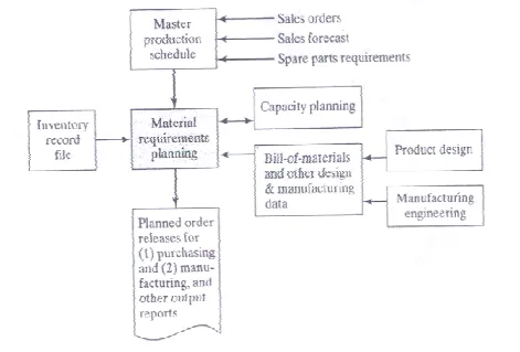
To function, the MRP program needs data contained in several files. These files server as inputs to the MRP processor. They are (1) the master production schedule, (2) the bill of materials file and other engineering and manufacturing data, and (3) the inventory record file. Figure 1 illustrates the flow of data into the MRP processor and its conversation into useful output report. In a properly implemented MRP system, capacity planning also provides input to ensure that the MRP schedule does not exceed the production capacity of the firm. This concept is elaborated further.
The MPS lists what end products and how many of each are to be produced and when they are to be ready for shipment. Manufacturing firms generally work on monthly delivery schedules, but the master schedule in our figure uses weeks as the time periods. Whatever the duration, these time periods are called time buckets in MRP. Instead of treating time as a continuous variable ( which of course , it is ), MRP makes its computations of materials and parts requirements in terms of the buckets.
The bill of material ( BOM ) file provides information the product structure by listing the components parts and subassemblies that make up each product, It is used to compute the raw material and components requirement for end products listed in the master schedule. The structure of an assembled product can be illustrated as in Figure 2. This is much simpler than most commercial products, but its simplicity will server for illustration purposes. Product PI is composed of two subassemblies, SI and S@, each of which is made up of components C1,C2 and C3, and C3, and C4,C5 and C6, respectively. Finally, at the bottom level are the raw materials that go into each component. The items at each successively higher level are called the parents of the items feeding into it form below. For example. SI is the parent of C1 ,C2 and C3. The product structure must also specify the number of each subassembly , component, and raw material that go into respective parent. These numbers are shown in parentheses in our figure.

The inventory record file is referred to as the item master file in a computerize inventory system. The types of data contained in the inventory record are divided into three segments.
1. Item master data : This provides the item’s identification ( part number ) and other data about the part such as order quantity and lead times.
2. Inventory status : This gives a time-phased record of inventory status. In MRP, its is import to know not only the current level of inventory but also any future changes that will occur against the inventory. Therefore , the inventory status segment lists the gross requirements for the item, schedules receipts, on-hand status, and planned order releases, as shown in figure 25.5.
3. Subsidiary data. The third file segment provided subsidiary data such purchase orders, scrap or rejects and engineering changes.
How MRP Works
The MRP processor operates on data contained in the MPS, the BOM file, and the inventory record file. The master schedule specifies the period-by period list of final products required. The BOM define what material and components are needed for each
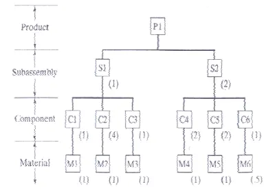
Figure 25.5 Initial inventory status of material M4 in Example 25.2
Product and inventory record files gives the current and future inventory status of each product, component, and material. The MRP processor computers how many of each component and raw material are needed each period by “ exploding “ the end product requirements into successively lower levels in the product structure.
Example 25.1 MRP Gross Quantity Computations
In the master schedule of Figure 25.2, 50 units of product PI are to be completed in week 8. Explode this product requirement into the corresponding number of subassemblies and components required.
Solution : Referring to the product structure in Figure 25.4, 50 units of P1 explode into 50 units of S1 and 100 units of S2. Similarly, the requirements for these subassemblies explode into 50 units of C1, 200 of C2, 50 of C3, 200 of C5 and 100 of C6. Quantities of raw materials are determined in a similar manner.
Several complicating factors must be considered during the MRP computations. First the quantities of component and subassemblies listed in the solution of Example 25.1 do not account for any of those items that may already be stocked in inventory or are expected to be received as future order. Accordingly, the computed quantities must be adjusted for any inventories on hand or on order, a procedure called netting. For each time bucket, net requirements = gross requirements less on hand inventories and less quantities on order.
Second, quantities of common use items must be combined during parts explosion to determine the total quantities required for each component and raw material in the schedule. Common use items are raw materials and components that are used on more than one product. MRP collects these common use items from different products to achieve economics in ordering the raw materials and producing the components.
Third, lead times for each item must be taken into account, The lead time for a job is the time that must be allowed to complete the job from start to finish. There are two kinds of lead times in MRP: ordering lead timed and manufacturing lead times. Ordering lead time for an item is the time required from initiation of the purchase requisition to receipt of the item from the vendor. If the item is raw material that is stocked by the vendor, the ordering lead time should be relatively short, perhaps a few days or a few weeks. If the items is fabricated, the lead time may be substantial, perhaps several months. Manufacturing lead time is the time required to produce the item in the company’s own plant, form order release to completion, once the raw material for the item are available. The scheduled delivery of end product must be translated into time-phased requirements for components and materials by factoring in the ordering and manufacturing lead time.
EXAMPLE 25.2 MRP Time Phased Quantity Requirements :
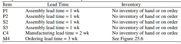
To illustrate these various complicating factors, let use consider the MRP procedure for component C4, which is used in product P1. This part also happens to be used on product P2 of the master schedule in Figure 25.2. The product structure for P2 is shown in figure 5.6. Component C4 is made out of material M4, one unit of M4 for each unit of C4, and the inventory status of M4 is given in figure 25.5. the lead time and inventory status for each of the other items needed in the MRP calculations are shown in the table below. Complete the MRP calculations to determine the time phased requirements for items S2,S3,C4 and M4, based on the requirements for P1 and P2 given in the MPS of Figure 25.2. we assume that the inventory on hand or on order for P1 , P2,S2,S3 and C4 is zero for all future periods except for the calculated valves in this problem solution.
Solution : The result of the MRP calculations are given in figure 25.7. the delivery requirements for P1 and P2 must be offset by their 1 wk assembly lead time to obtain the planned order released. These quantities are then exploded into requirements for subassemblies S2 ( for P1) and S3 ( for P1 ) and S3 ( for P2 ). These requirements are offer by their 1 wk assembly lead time and combined in week 6 to obtain gross requirements for component C4. Net requirements equal gross requirements for P1, P2,S2 and C4 because of no inventory on hand and no planned orders. We see the effect of current inventory and planned orders in the time-phased inventory status of M4. The on-hand stock of 50 units plus scheduled receipts of 40 are used to meet gross requirements of 70 units of M4 in week 3, with 20 units remaining that can be applied to the gross requirements of 280 units in week 4. Net requirements in week 4 are therefore 260 units. With an ordering lead time of 3 wk, the order release for 260 units must be planned for week 1.


MRP Output and Benefits :
The MRP program generates a variety of outputs that can be used in planning and managing plant operations. The output include (1) planned order releases, which provide the authority to place orders that have been planned by the MRP system: (2) report of planned order releases in future periods ; (3) rescheduling notices, indicating changes in due dates for open orders; (4) cancellation notices, indicating that certain open orders have been cancelled because in the MPS;(5) reports on inventory status; (6) performance reports of various types , indicating costs, item usage, actual versus planned lead times, and so on; (7) exception report , showing deviations from the schedule from the schedule, orders that are overdue, scrap, and so on; and (8) inventory forecasts, indicating projected inventory levels in future periods.
Of the MRP output listed above, the planned order releases are the most important because they drive the production system. Planned order of two kinds, purchase orders and work orders. Purchase orders provide the authority to purchase raw materials or parts from outside vendors, with quantities and delivery dates specified. Work orders generate the authority to produce parts or assembly subassemblies or products in the company’s own factory. Again , quantities to be completed and completion dates are specified.
Benefits reported by users of MRP systems include the following: (1) reduction in inventory, (2) quicker response to changes in demand than is possible with a manual requirements planning systems, (3) reduced setup and product changeover costs, (4) better machine utilization, (5) improved capacity to respond to changes in the master schedule, and (6) aid in developing the master schedule.
Notwithstanding these claimed benefits, the success rate in implementing MRP systems throughout industry has been less than perfect. Some MRP systems have not been successful because (1) the application was not appropriate, usually because the product structure did not fit the data requirements of MRP; (2) the MRP computations were based on inaccurate data; and (3) the MPS was not coupled with a capacity planning system, so the MRP program generated an unrealistic schedule of work orders that overloaded the factory.