An automated flow line consists of several machines or workstations which are linked together by work handling devices that transfer parts between the stations. The transfer of work parts occurs automatically, and the workstations carry out their specialized functions automatically. The flow line can be symbolized as shown in Figure1 using the symbols presented in Table1. A raw work part enters one end of the line and the processing steps are performed sequentially as the part moves from one station to the next. It is possible to incorporate buffer storage zones into the flow line, either al a single location or between every workstation. It is also possible to include inspection stations in the line to automatically perform intermediate checks on the quality of the work parts. Manual stations might also be located along the flow line to perform certain operations which are difficult or uneconomical to automate.
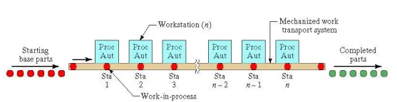
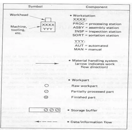
Figure ; symbols used in production systems diagrams
The objectives of the use of flow line automation are, therefore:
· To reduce labour costs
· To increase production rates
· To reduce work-in-process
· To minimize distances moved between operations
· To achieve specialization of operations
· To achieve integration of operations
Configurations of automated flow line.
1) In-line type The in-line configuration consists of a sequence of workstations in a more-or-less straight-line arrangement as shown in figure 1. An example of an in-line transfer machine used for metal-cutting operations is illustrated in Figure

Figure Example of 20 stations In-line
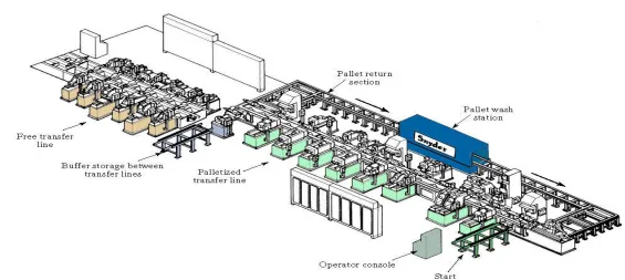
Figure Example of 20 stations In-line configuration
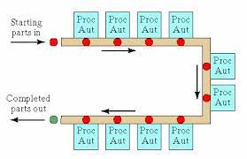
2) Segmented In-Line Type
The segmented in-line configuration consists of two or more straight-line arrangement which are usually perpendicular to each other with L-Shaped or U-shaped or Rectangular shaped as shown in figure. The flow of work can take a few 90° turns, either for workpieces reorientation, factory layout limitations, or other reasons, and still qualify as a straight-line configuration.
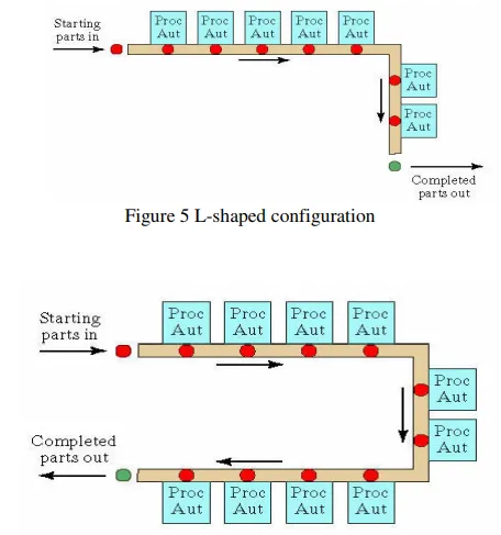
Figure U-shaped configuration
3) Rotary type
In the rotary configuration, the work parts are indexed around a circular table or dial. The workstations are stationary and usually located around the outside periphery of the dial. The parts ride on the rotating table and arc registered or positioned, in turn, at each station for its processing or assembly operation. This type of equipment is often referred to as an indexing machine or dial index machine and the configuration is shown in Figure and example of six station rotary shown in figure
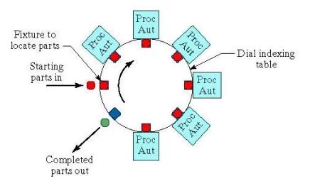
Figure 8 Rotary configuration
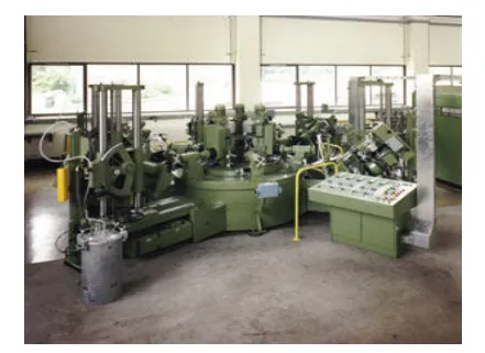
Example of 6 station rotary configuration