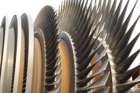
There are two basic types of steam turbines: Impulse and Reaction turbines. The impulse turbine is normally used for high and intermediate steam turbines, whereas the reaction turbine is used for low steam turbines. However modern turbines can also be a combination of these two types.
Steam Turbines in Power Plants
Overview
The type of rotating equipment we will look at in this article will be steam turbines used for power generation.The first steam turbine for this application was invented by Sir Charles Parsons, and his first one came on line in 1888. This was a great advancement from the other steam turbines around at the time as it was a revolutionary multi-stage turbine which used the expanded steam much more efficiently than the conventional single stage ones. We shall look therefore at a typical modern Parsons Turbine used to generate power for the National Grid, which at present is responsible for producing 80% of the world’s electricity.
Types of Steam Turbines
There are two basic types of steam turbines: Impulse and Reaction turbines. The impulse turbine is normally used for high and intermediate steam turbines, whereas the reaction turbine is used for low steam turbines. However, modern turbines can have a combination of these two types in the high/low pressure stages.
Steam Flow Through the Turbine
The sequence of steam passage through the turbine is as follows: (see image)
Superheated steam (above 500°C and 170bar) is injected into the high pressure (HP) stage of the turbine through a ring of static nozzles. These nozzles project the steam at the precise angle onto the rotor blades to extract the maximum energy from it.
The blades on the HP rotor are quite small and the diameter of the rotor gets larger from the steam entrance to the exit where it is redirected to the boiler to be reheated to 500°C. This reheated steam is injected into the intermediate stage (IP) of the turbine, in which, like the HP stage, the rotor gets progressively bigger in diameter from the steam entrance to exit (the blade sizes become larger as the pressure of the steam drops).
Finally the steam is directed into the LP section of the turbine where the blades are the largest, to accommodate the flow of lower exhaust steam from the IP. The steam exits the LP stages and enters the condenser, which is under a vacuum and, the resulting condensate is pumped back to the boiler by the feed pump.
Image

Assembly and Maintenance of Steam Turbines
Very fine clearances that are imperative to the efficient operation of the turbine exist between the rotating turbine blades and the fixed blades/nozzles. Therefore it is essential that great care be employed in assembly in order to maintain these tolerances. Another important point to be considered before assembling the rotor to the turbine is the balancing of the rotor, which is normally carried out by a specialist company. Also crucial to smooth running is the alignment of the turbine drive shaft to the generator drive shaft, which can be carried out using dial gauges or the more modern method of laser shaft alignment. With speeds of 3000 RPM for 50 Hz and 3600 RPM for 60 Hz, these measures along with the initial ‘bedding in’ of the main white metal bearings will ensure that no vibration takes place during operation.
Running a Steam Turbine up from Cold
Finally, there are strict procedures to be adhered to when the turbine is stationary and when running up from cold. It is essential that only superheated steam is used as any water can severely damage the blades. Because the condenser is normally under a vacuum, if a vacuum is applied when the turbine is off-line, the turning gear should be used to slowly rotate the shaft. This avoids the possibility of the vacuum bowing the turbine shaft. It is imperative to “warm through” the turbine inlet and exhaust steam system several hours before the turbine/generator is due to come on line. This is carried out (after disengaging the turning gear), by running the turbine for one minute at 10-15 RPM then stopping it for one minute before repeating. This ensures that all three stages of the turbine along with the pipework and pumps are fully expanded to working conditions and the lube oil is up to optimum temperature and pressure.


