Otto Cycle (1876) (Used S. I. Engines):
 |
| Fig: Engine and Indicator diagram |
Processes:
0-1 = Suction: The inlet valve is open, the piston moves to the right, admitting fuel-air mixture into the cylinder at constant pressure.
1-2 = Isentropic compression: Both the valves are closed; the piston compresses the combustible mixture to the minimum volume.
2-3 = Heat addition at constant volume (combustion): The mixture is then ignited by means of a spark, combustion takes place and there is an increase of temperature and pressure.
3-4 = Isentropic expansion: The products of combustion do work on the piston which moves to the right and pressure and temperature of the gases decreases.
4–1 = Constant volume heat rejection (Blow down): The exhaust valve open, and the pressure drops to the initial pressure.
1-0 = Exhaust: With the exhaust valve open, the piston moves inwards to expel the combustion products from the cylinder at constant pressure.
The series of processes as described above constitute a mechanical cycle and not a thermodynamic cycle. The cycle is completed in four strokes of the piston.
 |
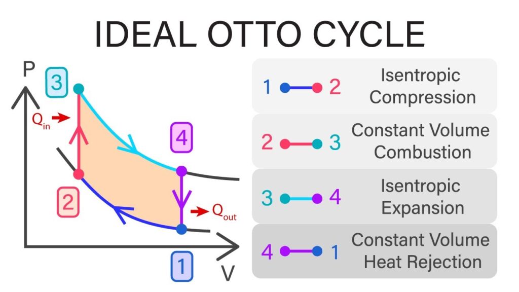
| Fig: Air standard otto cycle P-V and T-S diagram |
This cycle consists of two reversible adiabatic processes and two constant volume processes as shown in figure on P–V and T–S diagrams.
The process 1-2 is reversible adiabatic compression, the process 2-3 is heat addition at constant volume, the process 3-4 is reversible adiabatic expansion and the process 4-1 is heat rejection at constant volume.
The cylinder is assumed to contain air as the working substance and heat is supplied at the end of compression, and heat is rejected at the end of expansion to the sink and the cycle is repeated.
Air is compressed in process 1-2 reversibly and adiabatically. Heat is then added to air reversibly at constant volume in process 2-3. Work is done by air in expanding reversibly and adiabatically in process 3-4. Heat is then rejected by air reversibly at constant volume in process 4-1, and the system (air) comes back to its initial state. Heat transfer processes have been substituted for the combustion and blow down processes of the engine. The intake and exhaust of the engine cancel each other.
Let ‘m’ be the fixed mass of air undergoing the cycle of operation. Therefore,
Heat supplied, Q₁ = Q₂ – ₃ = mcv (T₃ – T₂)
Heat rejected, Q₂ = Q₄ – ₁ = mcv (T₄ – T₁)
Therefore, Efficiency, ɳ = 1 – (Q₂/Q₁) = 1 – [mcv (T₄ – T₁)/ mcv (T₃ – T₂)]
= 1 – [(T₄ – T₁)/(T₃ – T₂)]……………..eq. (i)
Process 1-2, T₂/T₁ = (V₁/V₂)ɣ-1
Process 3-4, T₃/T₄ = (V₄/V₃) ɣ-1 = (V₁/V₂)ɣ-1
Therefore, T₂/T₁ = T₃/T₄ or, T₃/T₂ = T₄/T₁
or, (T₃/T₂) – 1 = (T₄/T₁) – 1
Therefore, (T₄- T₁)/(T₃ – T₂) = T₁/T₂ = (V₂/V₁)ɣ-1…..substituting this value to eq.(i)
From eq. (i), we have, ɳ = 1 – (V₂/V₁)ɣ-1
or, ɳotto = 1 – 1/(rk)ɣ-1
Where, rk is called the compression ratio and is given by,
rk = volume at the beginning of compression/volume at the end of compression
= V₁/V₂ = v₁/v2
The efficiency of air standard otto cycle is thus a function of the compression ratio only. The higher the compression ratio, the higher is the efficiency. It is independent of the temperature levels at which the cycle operates. The compression ratio can’t, however be increased beyond a certain limit, because of a noisy and destructive phenomenon, known as detonation.
It is also depends upon the fuel, engine design and the operating conditions.