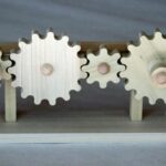
Simple Gear Train-
The simple gear train is used where there is a large distance to be covered between the input shaft and the output shaft. Each gear in a simple gear train is mounted on its own shaft.
When examining simple gear trains, it is necessary to decide whether the output gear will turn faster, slower, or the same speed as the input gear. The circumference (distance around the outside edge) of these two gears will determine their relative speeds.
Suppose the input gear’s circumference is larger than the output gear’s circumference. The output gear will turn faster than the input gear. On the other hand, the input gear’s circumference could be smaller than the output gear’s circumference. In this case the output gear would turn more slowly than the input gear. If the input and output gears are exactly the same size, they will turn at the same speed.
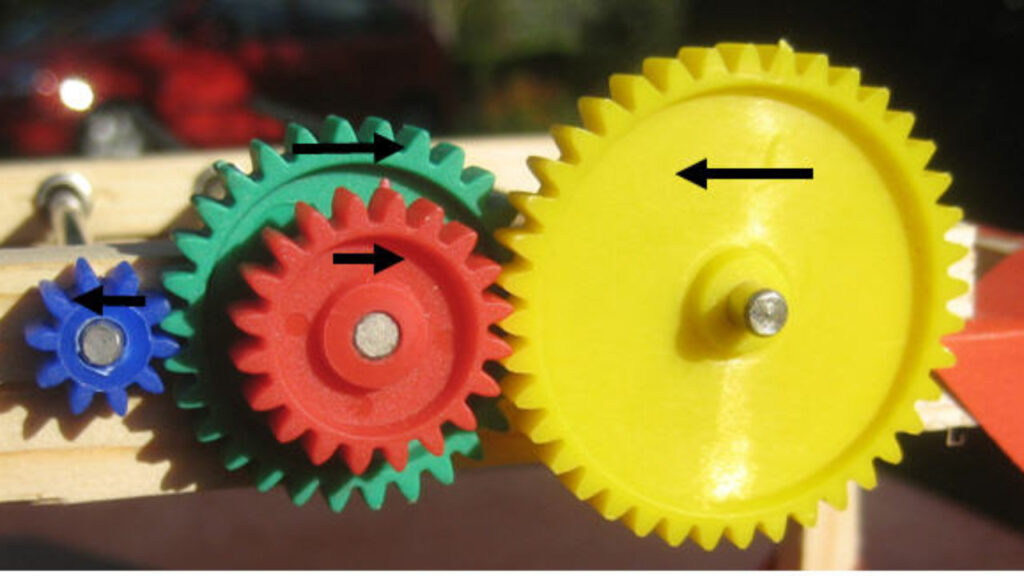
In many simple gear trains there are several gears between the input gear and the output gear.
These middle gears are called idler gears. Idler gears do not affect the speed of the output gear.
Compound Gear Train-
In a compound gear train at least one of the shafts in the train must hold two gears.
Compound gear trains are used when large changes in speed or power output are needed and there is only a small space between the input and output shafts.
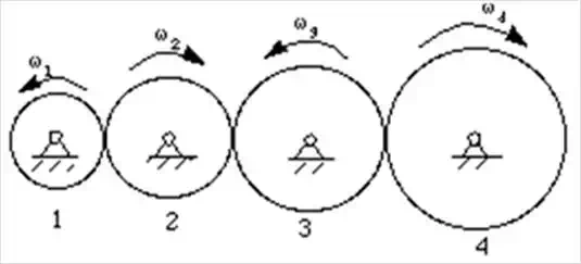
The number of shafts and direction of rotation of the input gear determine the direction of rotation of the output gear in a compound gear train. The train in Figure has two gears in between the input and output gears. These two gears are on one shaft. They rotate in the same direction and act like one gear. There are an odd number of gear shafts in this example. As a result, the input gear and output gear rotate in the same direction.
Since two pairs of gears are involved, their ratios are “compounded”, or multiplied together.
Example- The input gear, with 12 teeth, drives its mating gear on the counter-shaft, which has 24 teeth. This is a ratio of 2 to 1.
This ratio of DRIVEN over DRIVER at the Input – 2 to 1 – is then multiplied by the Output ratio, which has a DRIVEN to DRIVER ratio of 3 to 1.
This gives a gear ratio of 6 to 1 between the input and the output, resulting in a speed reduction and a corresponding increase in torque.