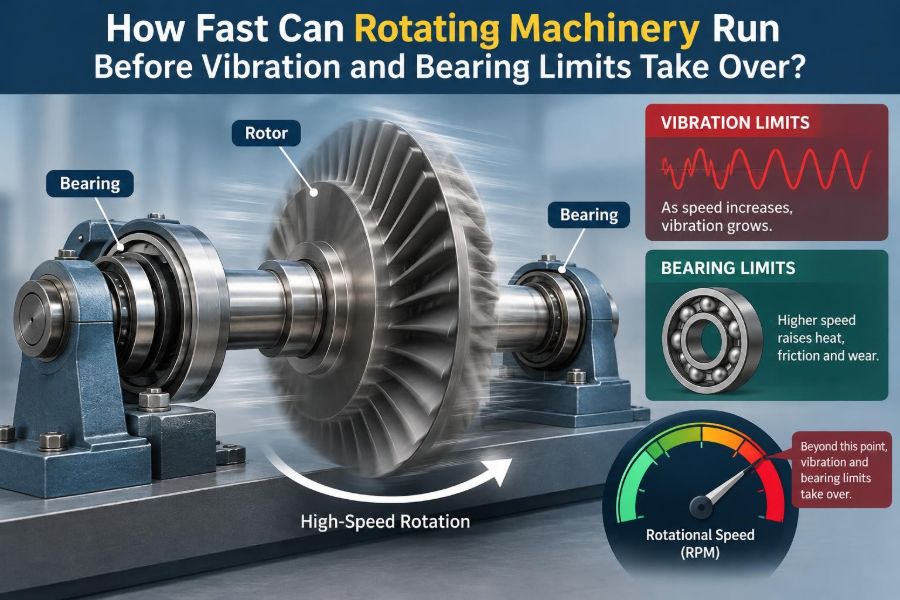

A small workshop fan can spin quietly for years. A centrifugal compressor, turbine, machine-tool spindle, or electric-motor rotor may spin far faster—and the consequences of a small defect are no longer small. A barely noticeable vibration at one speed can become a severe shake after a modest increase in rpm.
This creates a deceptively simple question: how fast can a machine run? The tempting answer is a single rotational-speed number. In practice, the answer depends on the rotor, bearings, support structure, balance quality, temperature, lubrication, drive system, and the speed range the machine must cross to get to its operating point.
Rotating machinery is rarely limited by one phenomenon alone. A shaft may be strong enough, while its bearings overheat. Bearings may be suitable, while a flexible support frame amplifies vibration. A rotor may operate safely at a high speed but be unable to pass smoothly through a critical speed on the way there.
Understanding these interactions helps engineers select equipment, diagnose problems, and avoid the costly habit of treating a rising vibration reading as merely a maintenance nuisance. Speed is a system-level design decision.
⚙️ Speed Is More Than an RPM Rating
Rotational speed is commonly stated in revolutions per minute, or rpm. It can also be expressed as angular velocity, usually in radians per second. The conversion matters because many stress, energy, and vibration relationships use angular velocity rather than rpm.
A manufacturer’s maximum speed is not automatically the speed a particular installation can safely sustain. It is typically tied to defined assumptions: a specified rotor, bearing arrangement, load, lubricant, cooling method, mounting condition, and allowable life or service duty.
The usable speed limit is the lowest relevant limit in the complete machine system. Increasing motor capability alone does not raise that limit.
🔄 Why Rotors Become Harder to Control at High Speed
At rest, a rotor’s mass distribution is simply geometry. During rotation, any offset between the mass center and the intended axis creates a centrifugal force. That force grows approximately with the square of rotational speed.
Doubling speed does not merely double the force caused by a given unbalance; it raises it by roughly four times. This is why a rotor that seems acceptable at low speed can become objectionable at high speed.
High speed also increases aerodynamic drag, lubricant churning, heat generation, and the sensitivity of the system to small manufacturing errors. These effects can interact rather than appear one at a time.
🎯 Unbalance: The Most Familiar Source of Rotating Force
Unbalance exists when the rotor’s center of mass does not lie on its rotating centerline. A slightly uneven fan blade, a missing balance weight, material buildup on an impeller, or an eccentric coupling can all create it.
For a simple rigid rotor, the unbalance force follows the relationship F = m × e × ω², where m is the unbalanced mass, e is its radius from the axis, and ω is angular velocity. The formula is simplified, but it captures the central speed-squared effect.
Balancing reduces the exciting force. It does not make the shaft infinitely stiff, correct poor alignment, or eliminate resonance in the supporting structure.
📏 Rigid Rotors and Flexible Rotors Behave Differently
A rotor is often called rigid when its operating speed stays below the range where appreciable shaft bending modes affect its behavior. It can usually be balanced in one or two correction planes and treated as a largely solid rotating body.
A flexible rotor bends significantly in operation. Its shape changes with speed, and its balance state may need correction in several planes. Many long, slender, or high-speed shafts fall into this category.
This distinction is practical rather than absolute. The same physical rotor may act rigid in a low-speed pump and flexibly when used at a much higher speed. A balance procedure suitable for one range may not control vibration in another.
🌊 Critical Speeds and the Resonance Problem
A critical speed occurs when a rotating excitation frequency aligns with a natural frequency of the rotor-bearing-support system. At that condition, relatively modest forcing can produce large motion because the system stores and exchanges vibratory energy efficiently.
The first critical speed is often associated with the first bending mode of a shaft. More complex machines can have several critical speeds, including modes involving the bearing housings, pedestal, casing, or foundation.
A critical speed is not automatically forbidden. Some machines are designed to operate below it, while others are designed to accelerate through it and operate well above it. What matters is the vibration response, damping, clearance, stability, and ability to cross the resonance safely.
🎻 Natural Frequency Depends on the Whole Support System
It is easy to calculate a shaft’s natural frequency in isolation and assume the job is done. In a real machine, bearings add stiffness and damping, housings flex, foundations move, couplings connect other inertias, and connected piping can constrain a casing.
A stiff rotor on a soft base can still have a low system natural frequency. Conversely, improving the pedestal, bearing support, or structural attachment can sometimes shift a troublesome resonance more effectively than changing the shaft itself.
That is why field vibration behavior can differ from a simple bench test. The machine is responding as an assembly, not as a drawing of a rotor alone.
🛣️ Passing Through a Critical Speed
A variable-speed machine may need to pass through a critical-speed region during every start and stop. The goal is usually not to dwell there. A sufficiently controlled acceleration can limit the time available for vibration to build.
However, “cross it quickly” is not a universal fix. Drive torque, load torque, controller behavior, machine clearances, and damping all matter. A machine that accelerates slowly under load may linger in a resonance zone despite a fast no-load run.
- Identify resonance zones during commissioning or testing.
- Set prohibited continuous-speed bands when the machine design requires them.
- Confirm that startup and shutdown sequences cross these bands predictably.
- Investigate any speed-dependent vibration peak rather than simply programming around it.
🧱 Stiffness, Damping, and Why Both Matter
Stiffness resists deflection. Damping dissipates vibratory energy. A system with high stiffness often has higher natural frequencies, but stiffness alone does not guarantee a low response at resonance.
Damping limits the amplification near a natural frequency. It can come from fluid-film bearings, structural joints, support materials, squeeze-film dampers, or other deliberately designed features. Too little damping can produce sharp resonance peaks.
Adding damping must be done thoughtfully. A soft isolation mount, for example, can reduce vibration transmitted to a floor but may introduce a low-frequency rigid-body mode that affects startup behavior.
🧭 Bearing Speed Limits Are Not a Single Number
Bearings support the rotor, locate it axially or radially, and transmit loads into the housing. Their speed capability depends on bearing type, size, preload or internal clearance, lubrication, applied load, cage design, cooling, and contamination control.
Catalog limits are useful screening values, not substitutes for a duty-specific analysis. Two bearings with the same bore diameter can have very different speed behavior because their rolling-element geometry and lubrication requirements differ.
Bearings also interact with rotor dynamics. Their stiffness and damping influence critical speeds and stability, so bearing selection can change more than temperature and fatigue life.
⚪ Rolling-Element Bearings Face Heat and Cage Constraints
Ball and roller bearings offer low friction, compact packaging, and good accuracy in many machines. At high speed, rolling contacts and lubricant shear generate heat. The cage, which separates and guides rolling elements, also experiences increasing dynamic demands.
As speed rises, internal sliding, centrifugal effects, grease behavior, and preload become more consequential. Excessive preload can improve stiffness but sharply raise heat generation; insufficient preload in some arrangements can allow undesirable motion.
A common screening parameter combines mean bearing diameter and speed. It is helpful for comparing applications, but it cannot account for every detail of lubricant delivery, heat removal, or transient behavior.
🛢️ Fluid-Film Bearings Enable Many Very High Speeds
Journal bearings support a shaft on a thin pressurized wedge of lubricant rather than on rolling contacts. Properly designed fluid-film bearings can carry heavy loads and work effectively in large, high-speed turbomachinery.
The shaft center does not sit perfectly centered while operating. It takes an equilibrium position in the oil film, and the film’s pressure distribution provides dynamic stiffness and damping. Those properties are central to rotor-dynamic design.
Fluid-film bearings need a reliable oil system, controlled oil temperature, suitable clearances, and clean lubricant. Their high-speed capability is not a reason to neglect startup, shutdown, or oil-supply failure scenarios.
💨 Lubrication Can Set the Real Speed Ceiling
Lubricant reduces friction and wear, but at high speed it can become a source of heat. Grease may churn, oil may shear, and excessive lubricant quantity can raise temperature rather than improve protection.
Oil-air, oil mist, circulating oil, jet lubrication, and grease lubrication are selected according to speed, load, geometry, environment, and maintenance needs. There is no universally superior method.
A bearing can fail at a speed that appears acceptable on paper if lubricant viscosity is wrong at operating temperature, delivery is inconsistent, or heat cannot leave the bearing housing. Measure temperature trends alongside vibration whenever possible.
🌡️ Thermal Growth Changes Clearances and Alignment
Rotors, housings, shafts, and supports rarely heat at the same rate. Differential thermal expansion changes internal bearing clearance, coupling alignment, seal gaps, and the load distribution between bearings.
Consider a motor and pump that are carefully aligned while cold. If one machine grows more vertically than the other after reaching operating temperature, the shaft centerlines can shift. The resulting misalignment may increase bearing load and vibration.
Thermal behavior should be considered during design and verified during operation. A machine that is smooth when cold but rough after warmup is providing a useful diagnostic clue.
📐 Alignment Protects Bearings but Does Not Cure Everything
Misalignment occurs when coupled shafts are offset, angled, or both. Flexible couplings accommodate limited movement, but they do not erase the forces created by excessive misalignment.
Typical consequences include elevated radial and axial bearing loads, coupling wear, seal distress, and vibration components related to rotational frequency and its harmonics. Thermal growth and soft foot can make a carefully performed initial alignment drift in service.
Alignment is essential maintenance, but it should not become the default explanation for every vibration problem. A resonance, bent shaft, bearing defect, looseness, or hydraulic excitation requires a different correction.
🪛 Mechanical Looseness Amplifies Small Defects
Loose hold-down bolts, worn fits, cracked supports, clearance in a bearing housing, or degraded grout can allow a machine to move nonlinearly. The resulting vibration can contain harmonics, impacts, and unstable changes with load or temperature.
Looseness often turns a manageable excitation into a much larger response. It can also shift natural frequencies, making the machine appear to develop a new critical speed after a support condition changes.
Do not attempt to solve structural looseness by adding balance weights. First restore the intended mechanical boundary conditions.
🌀 Aerodynamic and Hydraulic Forces Can Excite Vibration
Not all vibration begins with unbalance. Fans can experience blade-pass excitation, flow separation, or inlet distortion. Pumps can see pressure pulsations, recirculation, cavitation-related damage, or operation far from their preferred flow range.
Compressors may respond to aerodynamic instability, while turbines can have excitation related to nozzle or blade interactions. These forces occur at frequencies related to shaft speed, blade count, vane count, or flow dynamics.
A rotor may be well balanced and still vibrate because the process is exciting a structural mode. Measuring operating conditions alongside vibration is often what reveals the connection.
🔊 Frequency Analysis Reveals More Than Overall Vibration
An overall vibration value is useful for trending, but it combines many frequencies. A spectrum separates the signal into components and helps connect patterns to possible physical mechanisms.
A strong once-per-revolution component can be consistent with unbalance, although it is not proof by itself. Harmonics may suggest misalignment or looseness. Bearing defect frequencies, blade-pass frequencies, and electrical frequencies need interpretation using machine geometry and operating data.
A vibration spectrum is evidence, not a verdict. Reliable diagnosis checks phase, time waveform, operating condition, temperature, inspection findings, and the machine’s design.
📈 Speed Sweeps Turn Vibration Into a Map
A controlled run-up or coast-down test records vibration as speed changes. Plotting amplitude and phase against speed can reveal resonances, critical-speed regions, and whether a peak is tied to speed or to a separate process event.
A waterfall plot or cascade plot shows how the frequency content evolves over the speed range. It can distinguish a component that tracks shaft speed from one that remains at a fixed frequency.
Such testing must be planned within the machine’s safe operating envelope. It is not appropriate to force an unknown or damaged machine through suspected resonance without engineering review and suitable protection.
🧪 Rotor-Dynamic Analysis Is a Design Tool, Not Just Software Output
Rotor-dynamic analysis models the shaft, disks, bearings, supports, seals, and sometimes fluid forces to predict natural frequencies, mode shapes, response to unbalance, and stability margins. It is especially valuable for flexible rotors and high-energy machines.
The model is only as credible as its inputs. Bearing coefficients, support stiffness, rotor geometry, mass properties, and boundary conditions must represent the intended machine realistically.
Testing remains valuable because assemblies have tolerances and installation conditions. Analysis guides design choices; measurements confirm whether the built machine behaves as expected.
⚠️ Instability Is Different From Forced Resonance
Forced resonance occurs when an external periodic force, such as unbalance, drives the system near a natural frequency. Instability is different: the system can generate growing vibration through its own dynamic interactions.
In some fluid-film-bearing or seal systems, cross-coupled fluid forces can feed energy into shaft motion. The vibration may occur at a fraction of running speed and can grow as speed rises, even without a matching external forcing frequency.
This distinction matters because adding balance weight may reduce synchronous vibration but not solve an instability mechanism. Bearing design, seal design, damping, clearance, and operating conditions may need review.
🧮 Stress Limits Still Matter at High Speed
Vibration and bearings often receive the most attention, but rotor material stress can be decisive. Rotating disks, impellers, and rings experience centrifugal stress that rises strongly with speed.
Features such as keyways, sharp transitions, holes, corrosion pits, and manufacturing defects can concentrate stress. Repeated starts, stops, and speed changes add fatigue considerations, particularly where stress fluctuates.
Containment is another safety issue. If a high-speed component fails, surrounding guards or casings may need to manage released fragments. This is a design and risk-management matter, not a maintenance afterthought.
🧷 Overspeed Protection Addresses Abnormal Conditions
Overspeed can result from control failure, loss of load, incorrect drive settings, process upsets, or fault conditions in an energy source. The risk is especially serious where stored rotational energy is high.
Protection may include speed sensing, drive limits, independent trip functions, mechanical devices in some applications, and control-system logic. The appropriate architecture depends on machine type and the consequence of failure.
Protection does not justify routine operation near an uncertain limit. It exists to reduce exposure when normal control is lost or a fault develops.
🔌 Variable-Frequency Drives Change the Operating Picture
Variable-frequency drives make speed control accessible in many motor-driven machines. They also mean a machine may operate across a wider speed range than it did with direct grid-frequency operation.
That wider range can expose resonances that were previously never encountered. It can also move fans and pumps into process regions with pulsation, recirculation, poor cooling, or inadequate lubrication behavior.
Drive commissioning should include an agreed speed range, alarm behavior, acceleration ramps, and any skip bands. A skip band is useful only when it is based on understood behavior and does not conflict with process requirements.
🏭 A Pump Example: Why “Faster” May Not Mean Better
Imagine a centrifugal pump whose motor speed is increased to obtain more flow. The pump affinity relationships suggest that flow, head, and power all change with speed, but the mechanical consequences change too.
The higher speed can raise bearing load, vibration force from residual unbalance, seal surface speed, and hydraulic excitation. If the pump moves away from its preferred operating region, internal flow can become less stable and vibration may increase for reasons unrelated to balance.
The correct question is not merely whether the motor can turn faster. It is whether the pump, bearings, seals, casing, piping, motor, and process can support the new duty.
🧰 A Spindle Example: Precision Is Often the First Limit
In a machine-tool spindle, the first unacceptable effect may be loss of surface finish or tool life rather than a dramatic bearing failure. Runout, thermal growth, preload changes, and chatter can become limiting before a catalog speed ceiling is reached.
A spindle may use carefully controlled bearing preload, specialized lubrication, cooling, and a precisely balanced toolholder assembly. Changing tooling can change the rotating system enough to alter vibration behavior.
This illustrates a broader point: the allowable speed is often governed by the performance requirement. A rotor can remain intact while still being unable to do useful work at the required accuracy.
📊 What Different Limits Usually Look Like
| Limiting mechanism | Typical operational clue | Useful next check |
|---|---|---|
| Residual unbalance | Vibration rises strongly with speed, often near once per revolution | Balance condition, phase data, buildup on rotor |
| Critical speed | Distinct vibration peak over a narrow speed band | Run-up data, support stiffness, damping, mode shape |
| Bearing thermal limit | Temperature climbs with speed or preload/load | Lubricant, cooling, fit, preload, oil flow |
| Misalignment | Vibration and bearing distress after coupling or thermal changes | Cold and hot alignment, soft foot, coupling condition |
| Fluid-induced instability | Non-synchronous vibration that grows above a speed threshold | Bearing and seal dynamic behavior, clearances, oil condition |
| Process excitation | Vibration changes with flow, pressure, or load at similar speed | Operating point, pulsation sources, inlet and discharge conditions |
🔍 A Practical Method for Establishing a Speed Envelope
Start with the equipment manufacturer’s documented operating range and the design duty. Then identify what changes in the actual installation: rotor attachment, coupling, mounting, lubricant, cooling, process load, controls, and environment.
- Confirm rotor and attachment integrity, balance condition, and guarding.
- Verify bearing type, lubrication method, clearances or preload, and cooling capability.
- Review known critical speeds, prohibited ranges, and acceleration requirements.
- Check alignment, support stiffness, fasteners, piping loads, and foundation condition.
- Commission with measured speed, vibration, temperature, and relevant process data.
- Set alarm and trip strategies using the machine’s risk assessment and established operating guidance.
For machinery with significant stored energy or unclear behavior, involve qualified rotating-equipment and controls specialists. Field changes can invalidate assumptions made for the original configuration.
🚫 Common Shortcuts That Create Trouble
One shortcut is treating a bearing speed rating as the machine speed rating. Another is balancing a rotor without checking whether the vibration peak occurs only near a structural resonance.
Other frequent errors include using the wrong grease quantity, running a variable-speed machine continuously in a resonance zone, ignoring thermal alignment, and comparing vibration values from different sensor locations without context.
Replacing a failed bearing with the same part may restore operation, but it does not explain why it failed. Repeated failures are often evidence of a system problem: fit, contamination, load, alignment, lubrication, temperature, or vibration.
🛠️ Condition Monitoring Helps Preserve Margin
Trend data is generally more useful than a single isolated measurement. Vibration, bearing temperature, oil condition, speed, power, and process variables together show whether a machine is changing over time.
Baseline readings taken after proper installation provide a reference for later decisions. If a new vibration component appears after an impeller cleaning, coupling replacement, or drive update, the timing of the change is valuable evidence.
Monitoring does not replace inspection or engineering judgment. It helps direct attention before an operating margin disappears.
🧠 The Core Principle: Speed Must Be Designed as a System
There is no universal rpm at which vibration and bearing limits suddenly “take over.” Instead, every machine has several interacting boundaries: rotor stress, dynamic response, bearing heat and life, lubrication, support behavior, process forces, and functional accuracy.
A robust design keeps normal operation away from harmful resonances where practical, provides a safe path through unavoidable critical speeds, controls unbalance and alignment, and gives bearings the lubrication and thermal environment they need.
The most reliable answer to “How fast can it run?” is therefore conditional: it can run as fast as the validated rotor-bearing-support-process system can operate with acceptable vibration, temperature, stress, stability, and safety margin.
High rotational speed is not simply a motor setting; it is a carefully managed agreement between dynamics, bearings, structure, heat, and operating conditions. Respecting that agreement turns speed from a source of surprises into a usable engineering capability. ⚙️📈🛠️