
A machined aluminum bracket may look simple on a workbench: a few holes, a pocket, rounded edges, and perhaps a tapped thread. Yet before the first cutting tool touches metal, that bracket usually exists in several different forms—an idea, a 3D model, a manufacturing plan, machine instructions, and sometimes a live digital representation of the production process.
When one of those forms does not match the next, expensive problems appear. A designer may specify a corner that no available tool can cut. A programmer may select the wrong datum. An operator may discover that a fixture blocks access to a feature that looked perfectly reachable on screen.
Modern manufacturing software exists to reduce these handoff errors. It connects engineering intent to physical action, allowing teams to design, plan, simulate, make, inspect, and improve parts with far less guesswork.
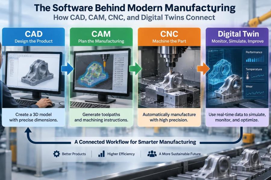
The familiar acronyms—CAD, CAM, CNC, and digital twin—are not competing technologies. They are connected stages in a larger information chain. Understanding that chain helps students see how products are made and helps working professionals diagnose where a process is losing time, quality, or knowledge.
🧭 The Digital Thread Through Manufacturing
A digital thread is the connected flow of information that follows a product from concept through design, production, inspection, service, and revision. It is not necessarily one software package; it is the ability for trustworthy data to move between people and systems.
For a machined part, the thread might begin with functional requirements, become CAD geometry and dimensions, then become CAM toolpaths and CNC code. Measurement results can return to the model or process plan, revealing whether the real part matches its intended design.
✏️ CAD Turns Intent Into Geometry
Computer-aided design (CAD) is where engineers define a product’s shape and, increasingly, its embedded design intent. A solid model describes faces, edges, holes, wall thicknesses, and relationships between features.
Unlike a static drawing, a parametric CAD model can preserve rules. If a mounting-hole pattern must remain centered when a bracket width changes, the model can encode that relationship. This makes revision faster, but only if the model is built logically rather than as a collection of unrelated dimensions.
📐 Dimensions Are More Than Numbers
Dimensions communicate size, but manufacturing needs more context: tolerances, surface finish, material, thread specifications, and geometric controls. A hole labeled 10 mm is incomplete if its allowed variation, location reference, and function are unknown.
Geometric dimensioning and tolerancing (GD&T) provides a structured language for this information. For example, position tolerance can define how accurately a hole must be located relative to datums, rather than forcing every coordinate to an unnecessarily tight limit.
🧩 Features Help Software Recognize Manufacturing Work
Designers often think in functional features—holes, pockets, ribs, bosses, slots, and fillets. CAM systems also benefit from feature recognition because each feature suggests possible machining operations.
A cylindrical hole may require drilling, boring, reaming, or tapping depending on size, tolerance, and thread requirements. Recognition is useful, but it is not a substitute for judgment: software may identify the shape while missing a critical requirement such as burr control or a delicate surface finish.
🏭 Design for Manufacturability Starts in CAD
Design for manufacturability (DFM) means shaping a part so it can be made reliably with the intended processes. A CAD model can be geometrically valid while still being costly or impractical to manufacture.
- Deep, narrow pockets may demand long tools that deflect and chatter.
- Inside corners smaller than a cutter radius may require special operations or leave uncut material.
- Features on many faces may require extra setups and more complex fixturing.
- Very tight tolerances should be reserved for surfaces whose function truly demands them.
Early discussion between design and manufacturing is often more valuable than correcting a completed program later.
🗂️ Drawings Still Carry Critical Information
Model-based definition is increasingly common, but 2D drawings remain useful in many organizations and supply chains. They provide a controlled, human-readable record of notes, views, tolerances, revision information, and inspection requirements.
The risk is having a drawing and model that disagree. Teams need a clear rule for which document is authoritative, along with revision control that prevents an older file from reaching the shop floor.
🔄 Revision Control Protects the Process
A small engineering change can affect tooling, inspection, assembly, and purchased material. Changing a hole from a clearance hole to a tapped hole, for instance, changes the required tools, machining sequence, and likely the inspection method.
Good revision control identifies what changed, why it changed, and which version is approved for manufacture. Naming a file “final_final_v3” is not a control system. A managed release process is.
🛠️ CAM Plans How Material Will Be Removed
Computer-aided manufacturing (CAM) converts geometry and manufacturing requirements into a practical machining plan. In subtractive manufacturing, this generally means defining stock, fixtures, tools, cutting strategies, machining order, and toolpaths.
CAM does not simply press a “make part” button. It supports choices. A programmer decides, for example, whether a pocket should be rough-machined with an adaptive toolpath, finished with a smaller cutter, and approached in a direction that protects a critical wall.
🧱 Stock, Setups, and Datums Define Reality
A CAM model must be placed in the same physical context as the workpiece. Stock is the raw material before machining; a setup defines how it is held and oriented; a work coordinate system connects the virtual model to the machine.
If the chosen datum is difficult to locate consistently on the real part, repeatability suffers. A robust setup uses accessible, stable reference surfaces and considers how the part will be located in later operations and inspected afterward.
🔧 Tool Selection Balances Competing Demands
Cutting tools are selected for material, geometry, reach, rigidity, required finish, machine capability, and productivity. A large end mill can remove material efficiently, but it cannot enter every corner. A small tool reaches detail, but it is less stiff and usually slower.
Tool choice also affects risk. Long tool overhang increases leverage, which can increase deflection, vibration, and breakage. The shortest tool that safely reaches the feature is often the better starting point.
🌪️ Toolpaths Control the Cutting Load
A toolpath is the planned route of a cutting tool. Its quality affects cycle time, tool life, surface finish, spindle load, and the chance of collision or chatter.
Modern roughing strategies often aim to keep cutter engagement more consistent. Instead of abruptly burying a tool in a corner, the path can use smoother arcs and shallower radial engagement. This may allow more predictable cutting, but suitable feeds, speeds, and machine dynamics still need to be verified.
🧮 Feeds and Speeds Need Context
Spindle speed, feed rate, depth of cut, and width of cut cannot be chosen from a single universal chart. Material condition, cutter coating, coolant delivery, toolholder rigidity, machine power, and the particular operation all matter.
A programmed value that works in a rigid production machining center may fail in a lighter machine or with a long-reach tool. CAM can calculate starting values, but responsible programming includes observing the actual cut and adjusting based on sound, chips, load, finish, and tool wear.
📮 Post-Processors Translate CAM for a Machine
CAM toolpaths are not usually sent directly to a CNC machine. A post-processor translates the CAM output into controller-specific code, commonly G-code and M-code.
The same intended motion can require different syntax, coordinate handling, cycles, or rotary-axis conventions on different controllers. A post-processor is therefore a critical bridge, not a minor export setting. It must match the machine configuration and be maintained when options or controls change.
🤖 CNC Executes the Manufacturing Instructions
Computer numerical control (CNC) uses programmed instructions to control machine motion and functions such as spindle rotation, coolant, tool changes, and probing. Typical machine types include mills, lathes, mill-turn centers, routers, grinders, and wire EDM machines.
CNC improves repeatability because the same instructions can be executed repeatedly. But repeatability is not the same as correctness: a wrong offset or incorrect program can repeat the same error very efficiently.
📍 Coordinate Systems Prevent Costly Misalignment
Several coordinate systems coexist in CNC machining. Machine coordinates describe the machine’s own reference framework. Work coordinates locate the part setup. Tool offsets account for individual tool lengths and, where applicable, radii.
Confusing these references is a common source of scrap and crashes. Before production, operators should verify that the programmed work offset, the actual fixture location, and the measured tool data all correspond to the approved setup.
🦾 Fixturing Is Part of the Program
A fixture is often treated as hardware separate from software, but it is integral to the digital process. CAM simulations must include clamps, jaws, vises, locating pins, and soft jaws because each can limit tool access or create a collision hazard.
A good fixture restrains the part against cutting forces without distorting it. Thin or flexible components may need carefully distributed support; clamping them too aggressively can produce a part that measures correctly while clamped and springs out of tolerance when released.
🛡️ Simulation Finds Problems Before Metal Is Cut
CAM verification simulates material removal and machine motion. It can reveal gouges, unmachined regions, excessive tool engagement, holder collisions, fixture interference, and unexpected axis travel.
Simulation is powerful only when its inputs are accurate. An outdated fixture model, incorrect tool assembly length, or missing machine limitation can create false confidence. The virtual setup must be maintained with the same discipline as the physical one.
🚦 Prove-Out Remains a Physical Check
A new program is normally proved out cautiously on the actual machine. This may include dry runs, reduced feed rates, single-block execution, tool-by-tool verification, and close observation of the first component.
Simulation reduces uncertainty; it does not eliminate it. Real materials vary, chips behave unpredictably, and a machine may have wear or backlash not represented in a model. Safe prove-out procedures protect people, equipment, and workpieces.
📏 Inspection Closes the Loop
Manufacturing is incomplete until the part is checked against its requirements. Inspection may use calipers, micrometers, gauges, optical systems, or coordinate measuring machines (CMMs), depending on the feature and required uncertainty.
Measurement results should do more than accept or reject a part. If a bore repeatedly trends toward one limit, the team can investigate tool wear, thermal effects, offset practices, or fixture behavior before parts become nonconforming.
📊 Process Data Turns Results Into Improvement
Machine alarms, spindle loads, tool-life records, probing results, cycle times, and inspection data can reveal patterns that are difficult to see one part at a time. The goal is not to collect every possible signal; it is to collect data that supports a decision.
For example, if a finish pass consistently needs a different offset after a certain number of parts, a tool-life policy may be more useful than repeatedly correcting the result after the fact.
🪞 What a Digital Twin Actually Is
A digital twin is a digital representation connected to a real physical asset, process, or system through data. In manufacturing, the twin may represent a machine, a fixture, a production cell, a part, or an entire factory workflow.
Not every 3D model is a digital twin. A static CAD model represents geometry. A twin gains value when it combines a model with relevant operational data and is used to understand, predict, test, or improve real behavior.
🏗️ Different Twins Serve Different Questions
Digital twins vary greatly in scope. A machine twin may track axis states and maintenance conditions, while a process twin may examine bottlenecks, changeover time, and part flow between operations.
| Type of representation | Main focus | Typical use |
|---|---|---|
| Product twin | Part geometry and requirements | Evaluate design changes and configuration |
| Machine twin | Machine behavior and condition | Plan motions or monitor operating state |
| Process twin | Operations, resources, and flow | Test routing, scheduling, and capacity choices |
| Factory twin | Multiple connected production systems | Explore layout and system-level trade-offs |
The appropriate twin depends on the decision at hand. Building a highly detailed factory model is not automatically useful if the immediate problem is a single unstable machining operation.
🔗 From CAD Model to Connected Twin
CAD supplies much of the product definition that a digital twin needs, while CAM contributes process intent: tools, setups, planned operations, and estimated machining time. CNC and inspection systems add what actually happened.
That connection allows comparison between planned and observed performance. If a simulated cycle time differs consistently from the real one, the difference may point to non-cutting motion, operator tasks, machine acceleration limits, or a process assumption that needs revision.
🧪 Virtual Commissioning Tests Automation Logic
Virtual commissioning uses a simulated environment to test parts of an automated system before installation or major changes. This can include robot paths, sensor logic, machine interlocks, conveyors, and sequence timing.
It is especially helpful when many devices must coordinate. A cell can appear correct when each machine is tested alone yet fail when a robot requests access while a door state, pallet position, or safety condition is not synchronized.
⏱️ Digital Twins Support Better Decisions, Not Magic Predictions
A twin can help engineers compare alternatives without disrupting production: different fixture concepts, order sequences, tool strategies, or layouts. It can also support maintenance planning when condition data and meaningful failure indicators are available.
However, predictions are only as credible as the model, assumptions, and incoming data. A twin should communicate uncertainty and be checked against actual outcomes. Treating an output as unquestionable because it came from software is a technical mistake.
🔐 Data Quality and Cybersecurity Are Manufacturing Issues
Connected machines create more paths for useful information—and more paths for incorrect or unauthorized information. Access control, backups, network segmentation, approved program release procedures, and clear ownership of data are practical manufacturing controls.
Data quality matters just as much. If tool identifiers differ between CAM, the tool crib, and the machine, automation can amplify the mismatch. Consistent naming, traceable revisions, and validation checks make integration dependable.
👥 People Remain Central to the System
Automation changes work; it does not remove the need for skilled judgment. Designers must understand function and manufacturing constraints. Programmers need process knowledge. Operators recognize unusual sounds, chip formation, and setup issues. Inspectors interpret measurement in relation to requirements.
The most effective environments treat these roles as connected contributors rather than separate departments passing files downstream. A machinist’s observation can improve a CAM template, and an inspection trend can prompt a CAD tolerance review.
⚠️ Common Breaks in the CAD-to-CNC Chain
Many manufacturing problems are not failures of advanced technology. They are gaps between systems and assumptions.
- Geometry without intent: a model lacks tolerances, material, or finish requirements.
- Uncontrolled changes: an updated model reaches CAM but not the inspection plan.
- Incomplete virtual setups: clamps, holders, or machine limits are omitted from simulation.
- Copied programs: old code is reused without confirming offsets, tools, and workholding.
- Ignored feedback: repeated measurement trends never reach design or programming.
Each break can be addressed with clearer workflows, but only if the organization treats information as part of the product.
🧰 A Practical Workflow for a New Part
A disciplined first-article workflow does not need to be bureaucratic. It needs clear checkpoints where the right person can catch the right kind of issue.
- Define function, material, critical features, and acceptance requirements.
- Create and review the CAD model with DFM and datum strategy in mind.
- Release controlled design data and create the manufacturing plan.
- Build CAM setups with accurate stock, fixtures, tools, and machine limits.
- Post-process, simulate, and review the CNC program.
- Prove out safely, inspect the first part, and document approved offsets and observations.
- Feed lessons from production and inspection into future revisions.
🎓 Skills Worth Building for Students and Professionals
Software proficiency is valuable, but transferable manufacturing skill comes from connecting digital decisions to physical consequences. Learn to read drawings, establish datums, understand basic cutting mechanics, and explain why a setup is repeatable.
Useful practice projects include modeling a simple part, creating a process plan, choosing tools, simulating toolpaths, and identifying inspection methods. Even without machine access, thinking through workholding, tolerances, and failure modes develops the habits needed on a shop floor.
🌐 The Core Principle: One Reliable Source of Intent
CAD, CAM, CNC, and digital twins work best when they preserve a coherent chain from what the part must do to how it is made and how performance is verified. The objective is not to digitize every activity for its own sake.
The objective is to make decisions using current, understandable, and traceable information. When a dimension, toolpath, setup, measurement result, and process change all point back to the same controlled intent, manufacturing becomes easier to improve.
Modern manufacturing succeeds when digital tools and physical expertise reinforce one another, turning engineering intent into repeatable, verifiable reality. The software provides the connection; disciplined people and processes make that connection trustworthy. ⚙️🏭📐