
A bracket inside an aircraft, a heat sink in a compact electronic device, or a fixture on a robotic production line may look ordinary from the outside. Yet each one carries loads, sheds heat, fits around other components, and must be made repeatedly without exceeding a cost target.
For decades, engineers addressed those demands with familiar shapes: plates, ribs, gussets, tubes, and machined pockets. These forms are effective because people understand them, can calculate them, and know how to manufacture them.
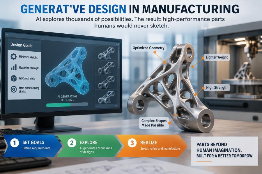
Generative design changes the starting point. Instead of sketching a likely shape and checking whether it works, an engineer defines the problem—loads, allowed space, material, manufacturing process, and performance goals—then lets software generate and evaluate many possible geometries.
The results can look organic, skeletal, or simply unconventional. The real breakthrough is not that software makes strange-looking parts. It is that design exploration can move from choosing among a few human concepts to systematically searching a much larger, constrained design space.
🧭 What Generative Design Actually Means
Generative design is a computational design process in which software produces candidate geometries from a set of engineering inputs and objectives. The engineer remains responsible for defining those inputs, reviewing results, and approving a design that can be manufactured, tested, and used safely.
A useful mental model is a route-planning app. You state the destination, constraints, and preferences; the software evaluates routes that would be tedious to compare manually. It does not know why you are travelling or whether a road closure is missing from its map. Likewise, generative design can search geometry efficiently, but it cannot replace engineering judgment.
📐 Why Humans Rarely Sketch These Shapes
Human designers often begin with forms that are easy to visualize and communicate. Straight beams, rounded corners, ribs, and symmetric housings align with drawing conventions, machining practices, and mental shortcuts developed through experience.
A computational search is not limited by those habits. If the load path bends around a keep-out zone, the software may create a branching structure that thickens only where stress requires it. Such a form can be difficult to imagine from a blank screen, even when it follows ordinary mechanics.
“Never sketch” does not mean “impossible for a human to design.” It means the geometry is unlikely to be the first, tenth, or even hundredth concept a person would draw without automated exploration.
🎯 Start With the Problem, Not the Shape
Traditional design commonly starts with an initial concept: perhaps an L-bracket with two ribs. Analysis then reveals whether it is stiff enough, light enough, or too highly stressed.
Generative design reverses the emphasis. The engineer first describes what must happen: support a load between two mounting points, avoid nearby equipment, limit deflection, conduct heat, or achieve a target natural frequency.
This shift is powerful because a computer can explore forms without treating the initial sketch as the default answer. It is also demanding: vague or incomplete requirements produce impressive-looking but potentially irrelevant outputs.
🧩 The Essential Inputs to a Generative Study
A generative study is only as credible as its boundary conditions. Before running it, teams typically define geometry that must remain, space that must stay empty, physical conditions, and the intended production method.
- Preserved regions: interfaces such as bolt holes, bearing seats, ports, and contact faces.
- Obstacle or keep-out regions: volumes needed for tools, wiring, motion, assembly, or adjacent components.
- Loads and constraints: forces, pressures, temperatures, supports, contacts, and motion limits.
- Objectives: for example, lower mass, higher stiffness, improved thermal performance, or reduced pressure drop.
- Manufacturing rules: constraints based on additive manufacturing, casting, milling, forging, or another process.
These are not administrative details. They are the engineering statement of the problem the algorithm will solve.
🧮 The Physics Beneath the Organic Appearance
Most structural generative workflows rely on numerical simulation, often finite element analysis (FEA). FEA divides a component into many small elements and estimates how the material responds to specified loading and constraints.
Areas that contribute little to stiffness may be reduced, while material is retained or redistributed along efficient load paths. The process is repeated until it approaches a solution that meets the mathematical goals and constraints.
The flowing appearance comes from stress distribution and optimization rules, not from an attempt to imitate bones or tree branches. Nature can offer useful analogies, but the generated geometry is governed by the model the engineer supplied.
🔄 Generative Design, Topology Optimization, and CAD Automation
These terms overlap, but they are not interchangeable. Clear language matters when selecting software, planning validation, or explaining a project to manufacturing teams.
| Approach | Primary purpose | Typical output |
|---|---|---|
| Topology optimization | Find an efficient material layout in a defined design space | A density-based or mesh-like concept requiring interpretation |
| Generative design | Generate and compare candidate designs under multiple goals and rules | Several manufacturable or near-manufacturable options with performance data |
| Parametric CAD automation | Rapidly vary dimensions or known features | Families of conventional CAD models |
In practice, commercial tools may combine all three. The key question is not the label on the tool but whether the workflow faithfully represents the engineering problem and delivers usable geometry.
🏗️ The Design Space Is a Physical Contract
The design space is the volume in which the algorithm may place material. It must be large enough to allow meaningful alternatives but realistic enough to fit the product.
Preserved geometry anchors the result to the real assembly. A mounting flange may remain unchanged because it mates with an existing frame. Keep-out zones prevent material from growing into a wrench path, cable corridor, moving linkage, or safety clearance.
A common failure is defining only the attractive load-bearing volume and forgetting access, service, and assembly. The resulting part may look structurally excellent while being unusable in the machine.
⚖️ Objectives Are Usually in Tension
Engineering rarely has one perfect objective. Reducing mass can lower stiffness. Increasing stiffness can increase material use. A design that is ideal for heat transfer may be difficult to clean or expensive to make.
Good workflows therefore use trade-offs rather than promises of a single optimum. A team might seek the lowest mass that stays below an allowable displacement and stress limit, while also remaining printable without inaccessible powder traps.
When tools display a set of alternatives, that is useful. It allows engineers to choose a practical point on the trade-off curve instead of treating the numerically best score as an automatic winner.
🧱 Material Models Matter More Than They Seem
The algorithm needs a material model: elastic modulus, strength-related limits, density, thermal properties, and sometimes fatigue behavior or nonlinear response. A result is valid only within the assumptions represented by that model.
Material data can vary with heat treatment, orientation, temperature, surface condition, and manufacturing route. This is especially relevant for additively manufactured metals, where process parameters and post-processing influence final properties.
Using a generic material entry may be acceptable for early concept comparison. It is not enough by itself for a component whose failure would create safety, reliability, or compliance consequences.
🖨️ Additive Manufacturing Unlocks More Geometry
Metal additive manufacturing, often called metal 3D printing, builds parts layer by layer. It can produce internal passages and branching structures that would be extremely difficult to machine from a solid block.
This makes additive processes a natural partner for generative design. A part can place material in curved, non-prismatic paths rather than being limited to the straight tool access required by conventional cutting.
But “printable” is not the same as “ready to print.” Orientation, supports, thermal distortion, surface finish, powder removal, inspection access, and post-machining all remain central design concerns.
🔩 Conventional Manufacturing Still Shapes the Answer
Generative design is not reserved for 3D printing. Constraints can guide designs toward forms suitable for machining, casting, forging, molding, or sheet fabrication.
For a milled component, the model may restrict undercuts and preserve tool approach directions. For casting, it may encourage appropriate wall transitions, draft, and accessible cores. For a forged part, material-flow and die-direction requirements influence what is realistic.
The result may look less dramatic than an additively manufactured lattice-like part. That is not a shortcoming. A manufacturable, affordable component is more valuable than an elaborate geometry that only exists in a render.
🛠️ Design for Additive Manufacturing Is Not Optional
Layer-based fabrication introduces constraints that a structural solver does not automatically understand unless they are specified. Downward-facing surfaces may need support structures, and enclosed cavities can trap powder or become impossible to inspect.
Engineers must also consider build orientation. Rotating a part changes which areas need support, affects thermal behavior during the build, and can influence anisotropy—direction-dependent properties produced by the layerwise process.
- Plan powder escape routes and cleaning access for internal channels.
- Reserve machining stock on critical faces, threads, and bores.
- Identify support-removal access before finalizing geometry.
- Specify inspection methods for features that cannot be directly measured.
🌡️ Thermal and Fluid Problems Need Different Thinking
Generative methods are not limited to brackets. They can also assist with heat exchangers, cooling plates, manifolds, ducts, and flow components by optimizing paths for heat transfer or fluid movement.
These applications need appropriate simulation models. A geometry that is structurally sound may create unacceptable pressure loss, stagnant flow regions, or fouling risk. Conversely, a thermally efficient channel may have walls too thin for pressure containment.
Multiphysics work combines such considerations, but it raises model complexity. Engineers should verify which phenomena are truly represented rather than assuming a visually intricate channel has been optimized for every requirement.
🧠 AI Can Assist, but It Does Not Certify a Part
Some design platforms use machine learning, cloud computing, or automated ranking alongside physics-based optimization. These capabilities can accelerate iteration and help organize large sets of candidates.
They do not eliminate the need for traceable assumptions, independent checks, engineering review, and physical validation. A model can only respond to represented variables; it does not inherently know a company’s maintenance practices, hidden assembly sequence, or unusual operating event.
Automation expands the search. Accountability remains human. This distinction is particularly important for safety-critical equipment and regulated industries.
🔍 A Simple Bracket Example
Consider a hypothetical bracket connecting two bolt locations to a loaded actuator. A conventional concept might use a machined plate with triangular ribs. It is simple to understand and may be exactly the right answer.
In a generative study, the engineer preserves the bolt bosses and actuator interface, defines the available envelope, applies expected load cases, restricts displacement, and selects a manufacturing process. The software may join the interfaces with curved struts and local reinforcement.
The next step is not to send that shape to production. The team checks bolt-load distribution, bearing stresses, vibration, fatigue, tool access, tolerances, installation clearance, and the consequence of less obvious load directions. The study provides a candidate; engineering turns it into a reliable part.
📊 Load Cases Cannot Be Chosen Casually
A component rarely experiences only one force in one direction. Startup, braking, transport, vibration, thermal expansion, operator misuse, and off-axis loading can dominate the design even if normal operation is mild.
If a generative run includes only the easiest load case, it will efficiently solve the wrong problem. Multiple load cases can be combined, weighted, or checked separately depending on the software and engineering intent.
Boundary conditions deserve the same scrutiny. An ideal fixed constraint is convenient, but a real bolted joint has contact compliance, preload, and possible slip. Simplification is necessary; unexamined simplification is risky.
📉 Stress Plots Require Interpretation
Color plots are persuasive, but they are not self-explanatory. A localized high stress may be a real notch effect, a mesh artifact, a singularity at an idealized sharp constraint, or evidence that the design needs refinement.
Engineers should inspect displacement shapes, reaction forces, mesh sensitivity, connection details, and load transfer—not just the peak value in a legend. They should also distinguish between nominal stress checks and the local behavior needed for fatigue assessment.
A smooth organic exterior can conceal abrupt thickness transitions, rough surfaces, or small radii that influence real-world durability. Simulation supports judgment; it does not excuse skipping it.
🧪 Validation Closes the Gap Between Model and Reality
Validation connects a digital design to physical performance. Depending on the application, it may include dimensional inspection, material testing, static proof loading, fatigue testing, vibration measurement, flow testing, thermal cycling, or nondestructive examination.
Validation should target the uncertainties that matter most. For example, an internally cooled printed component may need confirmation of channel cleanliness and pressure integrity, not only an external dimensional check.
For high-consequence parts, qualification plans are typically tied to the material, process, geometry, inspection route, and service conditions. There is no universal test sequence that makes every generatively designed part trustworthy.
📏 Tolerances Still Govern Assembly
Optimization often operates at a scale different from manufacturing tolerances. A solver may favor delicate branches or close gaps that are difficult to reproduce consistently, measure, or assemble.
Critical interfaces usually need conventional geometric control: flatness, position, diameter, surface finish, and datum strategy. It is common to preserve extra material and machine final mating surfaces after printing or casting.
Design teams should identify which dimensions control function. A lightweight body can be flexible in form, while bearing bores, sealing faces, and threaded interfaces may require tightly controlled, post-processed features.
💸 Cost Is More Than Material Volume
A lower-mass part does not automatically cost less. Complex geometry can add build time, support removal, machining, heat treatment, inspection, programming, and supply-chain qualification effort.
At the same time, a more expensive individual part may reduce system cost if it combines several components, removes fasteners, shortens assembly, improves energy use, or avoids a larger supporting structure. Cost must be considered at the system level.
The right comparison includes production volume. A generatively designed additive part may be attractive for a low-volume, high-value application, while a conventional formed or cast design can be more suitable when volumes justify dedicated tooling.
🔗 Part Consolidation Can Be a Major Benefit
One of the strongest uses of generative design is not simply making one part lighter. It can combine functions that were previously spread across several pieces: a bracket, cable guide, cooling path, and attachment feature, for example.
Fewer parts can reduce assembly operations and eliminate some joints. It can also reduce tolerance stack-up, where small dimensional variations accumulate across an assembly.
Consolidation has limits. A single integrated part may be harder to repair, replace, inspect, or source. The engineering decision should weigh lifecycle serviceability against the benefit of fewer interfaces.
♻️ Material Efficiency Has Nuance
Removing unnecessary material can reduce part mass and, in some contexts, reduce the material used in service. Weight reduction is especially meaningful when it affects moving systems, transport equipment, or structures that support other structures.
However, sustainability cannot be judged from mass alone. Energy use in a build process, failed builds, powder handling, post-processing, machining scrap, service life, and repairability all influence the overall picture.
A sound environmental assessment asks whether the design improves the whole lifecycle, not merely whether the final CAD model contains less volume.
🚧 Common Failure: Optimizing an Incomplete Requirement
The most common problem is not that the algorithm fails. It is that the original problem statement omits a requirement. Perhaps a technician needs room for a socket wrench, a cable must pass through the area, or a cleaning fluid must drain from an internal passage.
Prevent this by involving manufacturing, quality, service, and assembly stakeholders before launching a study. Their questions expose constraints that may never appear on a structural drawing.
A short requirements review can save far more time than repeatedly re-running an elegant but incomplete optimization.
🚧 Common Failure: Treating the First Result as Final CAD
Raw generative output may have faceted surfaces, thin members, irregular transitions, or features that need remodeling. It is often a high-value concept, not a release-ready model.
Engineers commonly rebuild or refine the geometry in CAD, adding radii, machining allowances, inspection features, drainage paths, and robust interface details. This can slightly change performance, so the refined model needs renewed analysis.
Do not polish away every unconventional feature simply to make the part look familiar. But do translate the concept into geometry that can be controlled and verified.
🚧 Common Failure: Ignoring Fatigue and Surface Effects
Many components fail after repeated loading rather than one large static event. Fatigue behavior is sensitive to stress concentration, residual stress, surface roughness, defects, and load spectrum.
Complex shapes can create local regions that are hard to finish or inspect. Additive surfaces may require machining, polishing, shot peening, heat treatment, or other process controls depending on the application and material.
Static stress optimization is a starting point, not a fatigue assessment. If cyclic service matters, fatigue requirements must be included from the earliest design stages.
🧰 A Practical Workflow for Engineering Teams
A disciplined workflow keeps generative design connected to real manufacturing decisions:
- Define function, failure consequences, loads, environment, interfaces, and service needs.
- Establish preserved regions, keep-out volumes, materials, and feasible manufacturing routes.
- Run concept studies with clearly stated objectives and constraints.
- Select candidates using performance, manufacturability, cost, and system-level criteria.
- Refine the geometry into controlled CAD and reanalyze the finished design.
- Plan process qualification, inspection, prototypes, and relevant physical tests.
- Release only when evidence supports the intended use.
Early prototypes are valuable because they reveal practical issues—access, fixturing, cleaning, handling—that a digital workflow may not capture fully.
👥 Collaboration Changes the Quality of the Result
Generative design crosses traditional departmental boundaries. Design engineers understand function; analysts understand model fidelity; manufacturing engineers understand process limits; quality teams understand measurement and traceability; technicians understand access and handling.
The best results emerge when these perspectives appear before, not after, the optimization run. A manufacturing constraint is not a late-stage compromise if it is built into the problem from the beginning.
For students, this is an important lesson: advanced software does not reduce communication needs. It makes precise communication about assumptions even more valuable.
📚 Skills Worth Building
Learning a generative-design interface is useful, but durable capability rests on fundamentals. Mechanics of materials, machine design, FEA interpretation, CAD modeling, tolerancing, manufacturing processes, and materials engineering all remain essential.
Useful habits include documenting assumptions, checking units, questioning boundary conditions, and comparing automated results with simple hand calculations. A basic free-body diagram can catch an incorrect setup before a large simulation consumes time.
Working professionals can start with a modest, low-consequence component. The goal is to build a repeatable validation workflow, not to choose the most visually complex part in the product.
🔮 Where Generative Design Fits Best
Generative methods are most compelling where performance constraints are demanding, geometry freedom is valuable, and the cost of engineering effort is justified. Examples may include aerospace structures, specialized tooling, medical devices, robotics, thermal management, and low-volume industrial equipment.
They are less compelling when a simple standard shape meets every requirement at low cost. A welded frame, extruded profile, stamped bracket, or conventional machined block may remain the better answer.
The mature question is not “Can we use generative design?” It is “Does this problem benefit enough from expanded design exploration to justify the modeling, manufacturing, and validation effort?”
🧭 The Core Principle: Search Broadly, Validate Rigorously
Generative design broadens the set of forms engineers can consider. It can reveal efficient load paths, integrate functions, and challenge assumptions built into familiar design templates.
Its value comes from pairing computational exploration with disciplined engineering: realistic requirements, credible physics, process-aware constraints, careful refinement, and physical evidence where needed. Strange geometry is not proof of innovation, and conventional geometry is not proof of missed opportunity.
The best generative design is not the most alien-looking part; it is the part that meets its real function reliably, can be made and inspected responsibly, and improves the system around it.
When engineers use the technology as a rigorous search tool rather than a shape generator, it becomes a practical extension of engineering judgment—one capable of finding solutions that were always physically possible, but rarely visible from a blank sketchpad. ⚙️🧠🏭