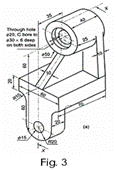
Problem 1- Sectional Orthographic Projection – Draw the Sectional Orthographic Projections of the object given in figure-3 Draw (1) Sectional Front View (2) Top View (3) L.H.S.V.
Procedure:
Step-1 Draw a horizontal x-y line of some suitable length. And x’-y’ line perpendicular to preciously drawn x-y line and give the point O at the intersection of the two lines.
Step-2 In this problem the Sectional Front View, Top View and Left Hand Side View have to be drawn in 1st angle method of projection (By default it is 1st angle method of projection), so first find out the total length, total height and total width from the isometric drawing given above. The total length is the length of the base of the front view, i.e., form X direction. The total height is the height in the front view and the total width is the length of the base in the side view.
Step-3 The total length is 75 mm, total height is 165 mm and the total width is 60 mm.
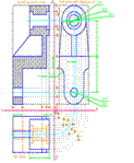
Step-4 Draw three boxes with light straight lines at respective location in such a way that the views should be in 1st angle method of projection. And these boxes should be at least 10 mm away from the x-y & x’-y’ lines.
Step-5 Then start the drawing by Sectional front view and within the respective box with dimensions, and it should be drawn with medium dark lines or curves. Like in this way draw all the required view and look for the hidden lines, which are drawn as dashed line. But the drawing should be drawn by transferring the projectors only wherever possible.
Step-6 Give the dimensions by any one method of dimensions and give the name of the views, as shown in the figure.